


14
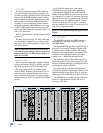
X.200
Digital X Bus
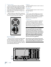
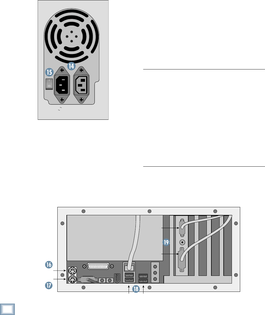
15. Power Switch
This one is self-explanatory. When the POWER
switch is turned ON, power is supplied to the Digital
X Bus and it boots up. When turning off the Digital
X Bus, you should select SHUTDOWN from the File
menu. At the end of the shutdown procedure, the
Digital X Bus lets you know when it is okay to turn
off the power switch.
Before turning on your Digital X Bus, please read
the “Power-up Procedure” section on page 55 of this
manual for complete step-by-step instructions.
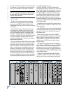
MOUSE
KEYBOARD
VGA
DVI
USB PORTS
115V 9
V 9
amp 6
p 6
0Hz
230V 4.5
V 4.5
amp 5
p 5
0Hz
1100
1100
W M
W M
ax
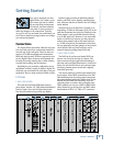
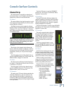
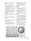
16. Mouse
This 6-pin miniDIN connector is used to connect a
PS/2 style mouse.
17. Keyboard
This 6-pin miniDIN connector is used to connect a
PS/2 style keyboard.
18. USB
These are four additional USB ports for connect-
ing more USB devices to the Digital X Bus. If you
are connecting a USB CD-ROM drive or a USB MIDI
interface, use one of these ports rather than the
USB ports on the rear panel (13).
19. Video Card
The video card has two connectors, one for each
touchscreen. The upper connector is a VGA-type
and connects to the left touchscreen, while the
lower connector is a DVI-type and connects to the
right touchscreen. You can use two video splitters to
connect two external displays, if desired.
Note: The fi rst production run of X.200s requires
that the external monitors be rotated 180º be-
cause the video signal is upside down. While
testing the touchscreen displays, we determined
that the clarity was better at the required viewing
angle if the touchscreen displays were mounted
upside down. If you are using external fl at-panel
LCD or plasma displays, this is not a problem.
However, conventional CRT-type displays gener-
ally will not work in this application.
Also note that the “touch” function does not work
with an external display. This feature is built into the
actual touchscreen displays on the Digital X Bus.
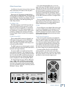
More Connections
There are even more connections available behind
the removable panel on the back of the Digital X
Bus. Use a small-headed Phillips screwdriver to re-
move the ten screws securing the panel to the chas-
sis to access these additional connections, which we
call the Motherboard Access Area.