


9
Owner's Manual
Owner's Manual
Getting Started
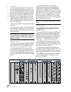
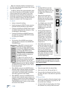
Each mic input provides an individual phantom
switch (+48 VDC), and a digitally controlled input
trim. All these controls are found in the I/O Confi gu-
ration window.
Each line input on the Mic/Line 4 card has a cor-
responding –10 dBv/+4 dBu jumper (J10-J13) on the
card that determines the input level reference point.
These jumpers come pre-installed from the factory
at a +4 dBu input level. However, if you have unbal-
anced or low line-level sources, you may choose to
remove these jumpers and set the input reference
to –10 dBv to better use the headroom of the mixer.
You can physically see these jumpers on the printed
circuit board of the card itself, and they can be
removed simply by pulling them off the card.
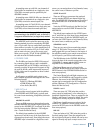
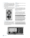
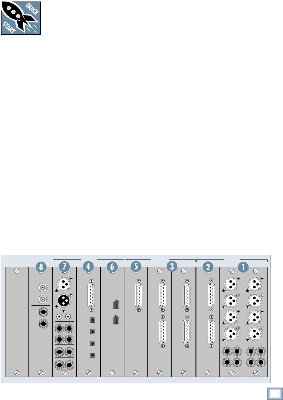
2. MIC/LINE 8 CARD
The Mic/Line 8 card has two female DB25 con-
nectors, one for inputs and one for outputs. The
input connector accepts eight balanced analog in-
puts that can be switched between mic- or line-level
inputs. As with the Mic/Line 4 card, each mic input
provides a phantom power switch and a digitally
controlled input trim.
The output connector provides eight balanced line-
level outputs. These DB25 connectors use the TAS-
CAM standard pinout for analog signal connections
(the same standard used on the analog cards for the
Mackie D8B and Hard Disk Recorder). If you are
connecting these to another device using the same
DB25 standard, you can use a DB25-to-DB25 audio
cable. Otherwise, you will need to use DB25 cables
that breakout to XLR, 1/4" TRS, or TT connectors.
Once you’ve unpacked your new
Digital X Bus, you’ll want to posi-
tion it where you can sit comfort-
ably and reach the touchscreens
and controls, and have relatively
easy access to the rear panel, in case you need to
make any changes to the connections. Typically,
once you’ve set it up and made the connections, you
won’t have to make any changes unless you change
your external equipment.
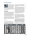
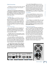
Connections
The Digital X Bus comes with a Mix Out card (con-
trol room card) and a Sync card already installed in
the card cage in the rear panel. There are also con-
nections for a USB mouse/keyboard, footswitches,
MIDI and other fun stuff. While not required to oper-
ate the Digital X Bus, the mouse and keyboard can
be handy for quickly entering data or when clicking
is easier than touching (the touchscreen).
Depending on your particular confi guration and re-
quirements, we have a variety of analog or digital I/O
cards that you can install in the card cage to suit your
application. Here’s a quick run-down of what we offer:
I/O Cards
1. MIC/LINE 4 CARD
This card has four female XLR balanced micro-
phone inputs, and four 1/4" TRS balanced/unbalanced
line-level inputs, for a total of eight analog inputs.
Note that this card does not provide any outputs.
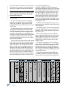
WORD
CLOCK
SYNC CARD
IN
OUT
IN
OUT
SMPTE
A
B
MIX OUT CARD
SPDIF
SPEAKERS
PHONES
MIX OUT
IN
OUT
IN
LR
12
LR
LR
OUT
AES/EBU
FIRE CARDDIGITAL CARD
OPTICAL
TDIF
I/O
IN A
IN B
OUT A
OUT B
MIC/LINE 4 CARD
5
7
6
8
1
2
3
4
MIC/LINE 4 CARD
5
7
6
8
1
2
3
4
MIC/LINE 8 CARD
IN
OUT
I/O
AES CARD
OUT
IN
LINE CARD
OUT
LINE CARD
IN
SYNC C • SLOTSD • SLOT B • SLOTS A • SLOTS