


68
X.200
Digital X Bus
• Draw a digital word clock fl ow chart for your
system. This will help you verify a logical
connection scheme. One piece of equipment
connected incorrectly can mess up your entire
system. Rats!
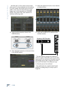
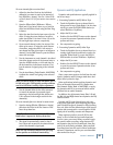
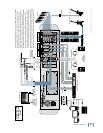
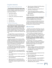
The following illustration shows a common sync
setup, using the Digital X Bus as the master word
clock source and a hub to distribute to other digi-
tally connected devices.
Modular Digital Multitrack
Modular Digital Multitrack
Sync Hub
Digital X Bus
Master Word Clock
Out From Digital X Bus
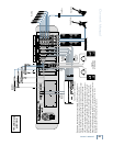
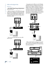
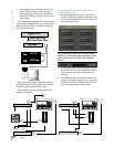
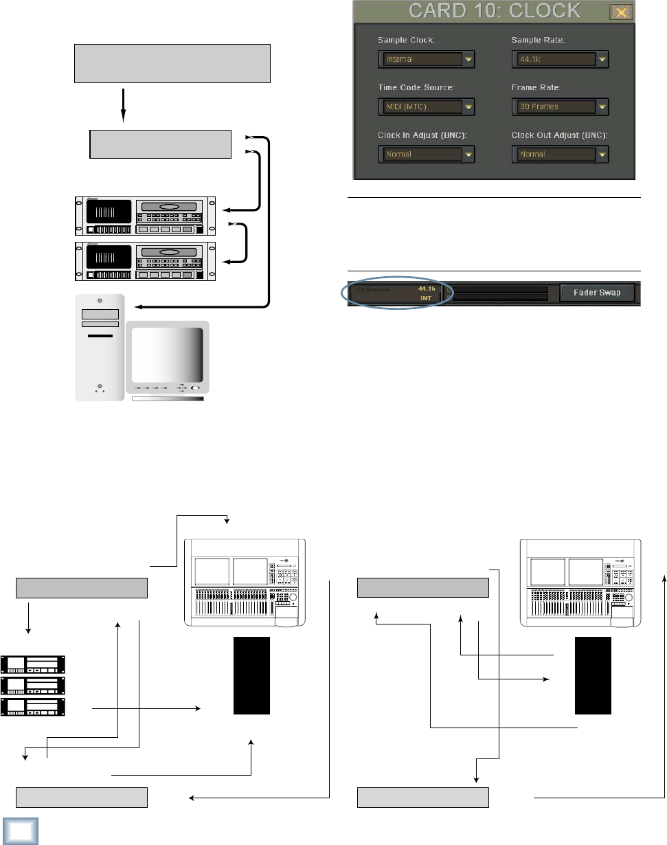
Here are two more sample setups that include
the Digital X Bus and other digital devices which
depend on accurate and solid word sync.
Use expensive, properly impedance-matched
cabling! It’s worth it!
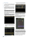
Verifying Word Clock Sync Between Devices
and the Digital X Bus
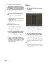
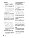
• When the Digital X Bus is set to “Internal” in
the Clock Card Setup window, it generates word
clock as a master device. All other devices must
be connected as slaves.
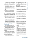
Tip: A quick way to open the Clock Card Setup
window is to touch the sample rate display in the
upper-right part of the screen, next to the L/R
meters.
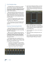
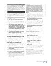
• If the Digital X Bus is slaved properly to a mas-
ter word clock source, the sample rate indicator
in the top menu bar (right screen) lights con-
tinuously.
• If the Digital X Bus is improperly connected as
a slave to the digital network, or not receiving a
valid Word Clock at the WORD CLOCK IN con-
nector, the sample rate indicator blinks.
9-pin
OUT
MIDI
IN
MIDI
OUT
MIDI
IN
MIDI
OUT
DTP
Word
Clock
INPUT
Word
Clock
INPUT
Word
Clock
OUTPUT
MTP
AV
Word
Clock
OUTPUT
9-pin
IN
Control
Track IN
Control
Track 1
9-pin
OUT
PCI-324
9-pin IN
Computer
Computer
MIDI
IN
MIDI
OUT
PCI 324 card
output
From PCI
MIDI
IN
MIDI
OUT
2408
MTP
AV
Word Clock
OUTPUT
Word Clock
OUTPUT
Word Clock
INPUT
Computer
Computer