


83
Owner's Manual
Owner's Manual
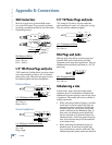
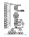
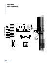
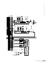
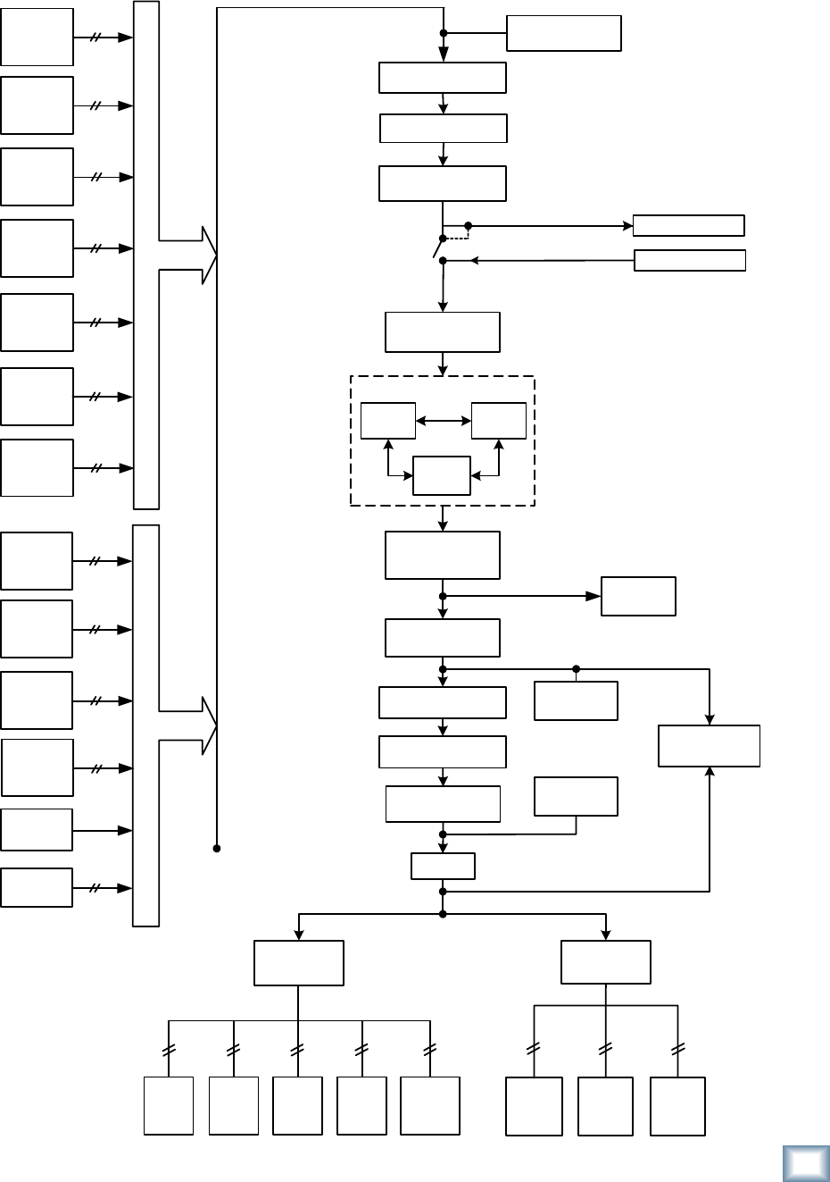
Digital X Bus
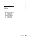
X.200 Signal-Flow Diagram
Channel
Input
Bus
Assign
Hardware
Destination
Software
Patch
Control
Room /
Phones
Mic/
Line 8
Line
Card
Digital
Card
AES
Card
FireWire
Card
x 8
x 8 x 8
x 8 x 24*
x 72
x 10
Mic/Line 8
Mic/Line 4
Line
Card
Digital
Card
AES
Card
FireWire
Card
Mix Out
Card
x 8
x 8
x 8
x 8
x 8
x 24 *
x 4
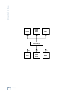
HAR
DWARE
INPUT S
OUR
CES
Channels
Busses
Aux Send
Masters
Talkback
Mic
Oscillators
x 72
x 8
x 12
x 3
SOF
TWARE
INPUT S
OURC
ES
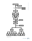
Channel Input
Source (x72)
Digital Trim
Channel Delay
(0-500ms)
Solo Bus
Channel Mute
Hardware Output
Hardware Input
ASSIGNMENT
SWITCH
Input Meter
Floating Insert, Send
Floating Insert, Return
PFL SOLO
Pre-DSP
Insert
Post-DSP
Insert
EQ
Comp/
Lim
Gate/Exp
Channel DSP
Pre-Aux
Send (1-12)
Direct Output
Hardware
Output
Channel Fader
AFL SOLO
Panner
Pre-Fader
Meter
Aux Returns
(VSTs)
Phase
Post-Fader
Meter
+
* channel count measured at 44.1-48kHz
+ exact number of VST returns available is determined by VSTs used
Post-Aux
Send (1-12)
x 12