


141
MASTER Chapter 8 Parameter Guide
Chapter 8
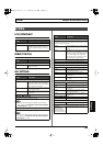
*1 The TRIGGR, TIME, and CURVE parameters are enabled when
the SOURCE parameter is set to INTRNL PEDAL.
*2 The RATE and FORM parameters are enabled when the
SOURCE parameter is set to WAVE PEDAL.
*3 The INPUT SENS parameter is enabled when the SOURCE
parameter is set to INPUT LEVEL.
Parameter/
Range
Explanation
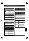
MAX (Maximum)
This sets the maximum value for the range in which the parameter
can change.
The value differs depending on the parameter assigned for TARGET
PARAMETER.
SW MODE (Switch Mode)
This sets the behavior of the value each time the switch is operated.
MOMENT The setting is normally OFF (minimum val-
ue), switching to ON (maximum value)
while the footswitch is held down.
LATCH The setting alternately switches to OFF
(minimum value) and ON (maximum val-
ue) each time the footswitch is pressed.
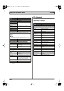
RANGE LOW, RANGE HIGH
Low: 0–126
High: 1–127
You can set the controllable range for target
parameters within the source’s operational
range. Target parameters are controlled
within the range set with RANGE LOW and
RANGE HIGH. You should normally set
RANGE LOW to 0 and RANGE HIGH to
127.
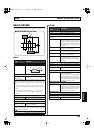
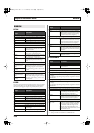
TRIGGR (Trigger)
This sets the trigger that activates the internal pedal. *1
PATCH CHANGE Functions when patches are switched.
GK VOL Functions when the divided pickup’s vol-
ume knob is adjusted.
GK S1, S2 Functions when the divided pickup’s
DOWN/S1 or UP/S2 switch position is
changed.
CTL1–CTL4 Functions when the CTL 1, 2 buttons or foot
switch connected to CTL 3,4 jack are operat-
ed.
EXP PEDAL Functions when the expression pedal con-
nected to EXP PEDAL jack are operated.
D BEAM V, H Functions when the vertical or horizontal
position is detected by the D Beam control-
ler.
RIBBON ACT, POS Functions when the ribbon controller is op-
erated by touch or when the position is de-
tected.
FC-300 EXP1, EXP2 Functions when the FC-300’s EXP PEDAL 1
or 2 is operated.
FC-300 CTL1, CTL2 Functions when the FC-300’s CTL1 or CTL2
is operated.
FC-300 E3/C3, CTL4,
E4/C5, CTL6, E5/C7,
CTL8
Functions when a pedal connected to the
FC-300’s E3/C3, CTL4, E4/C5, CTL6, E5/
C7, or CTL8 jacks is operated.
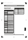
TIME
0–100,
BPM –
Adjusts the amount of time for the internal
pedal to shift from the fully released posi-
tion (pedal toe raised) to the fully depressed
position (pedal toe pressed down). *1
Parameter/
Range
Explanation
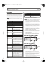
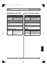
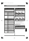
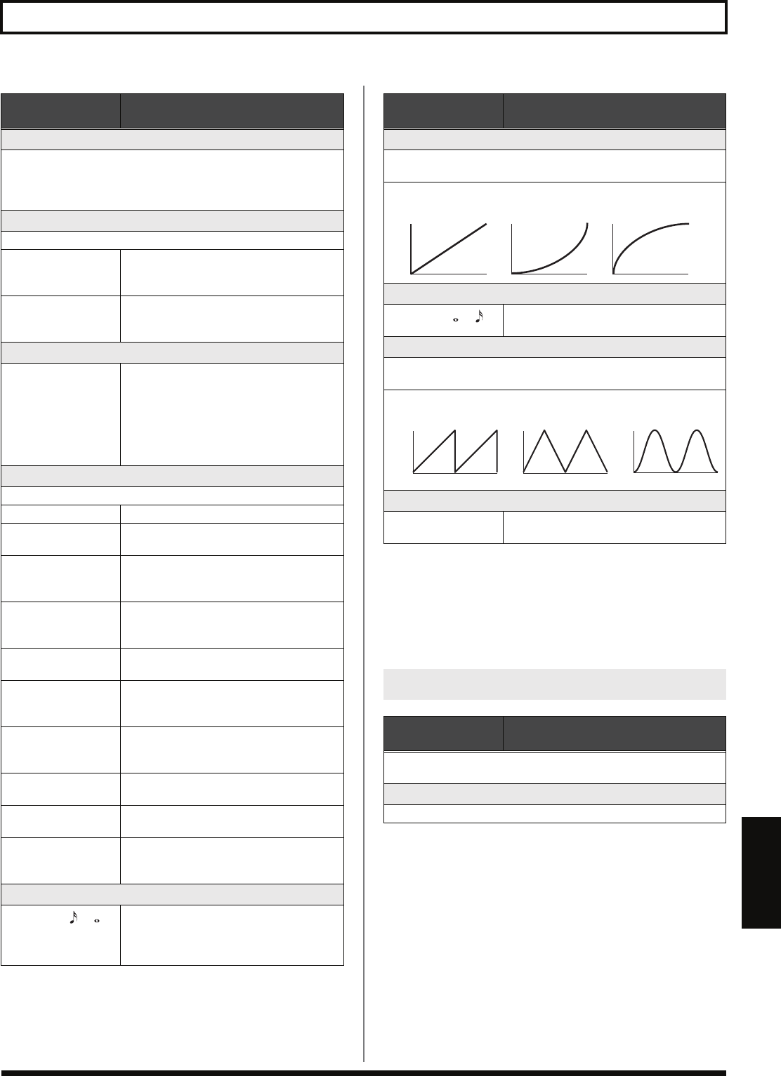
CURVE
This selects one of the three types that determines how the internal
pedal should change. *1
RATE
0–100,
BPM –
This determines the time spend for one cycle
of the wave pedal. *2
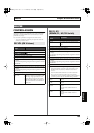
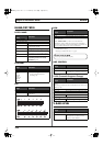
FORM
This selects one of the three types that determines how the wave
pedal should change. *2
INPUT SENS
0–100
This adjusts the input sensitivity when IN-
PUT LEVEL is selected for SOURCE. *3
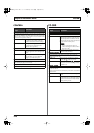
DIRECT EDIT F1–F6
Parameter/
Range
Explanation
This assigns functions to the function buttons operable in the Play
screen and the [F1]–[F6] or F1–F6 knobs.
TARGET PARAMETER
This selects the parameter to be changed.
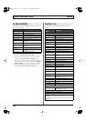
LINEAR SLOW RISE FAST RISE
SAW
TRI
SIN
VB-99_e.book 141 ページ 2008年8月18日 月曜日 午後1時10分