


149
SYSTEM Chapter 8 Parameter Guide
Chapter 8
MIDI
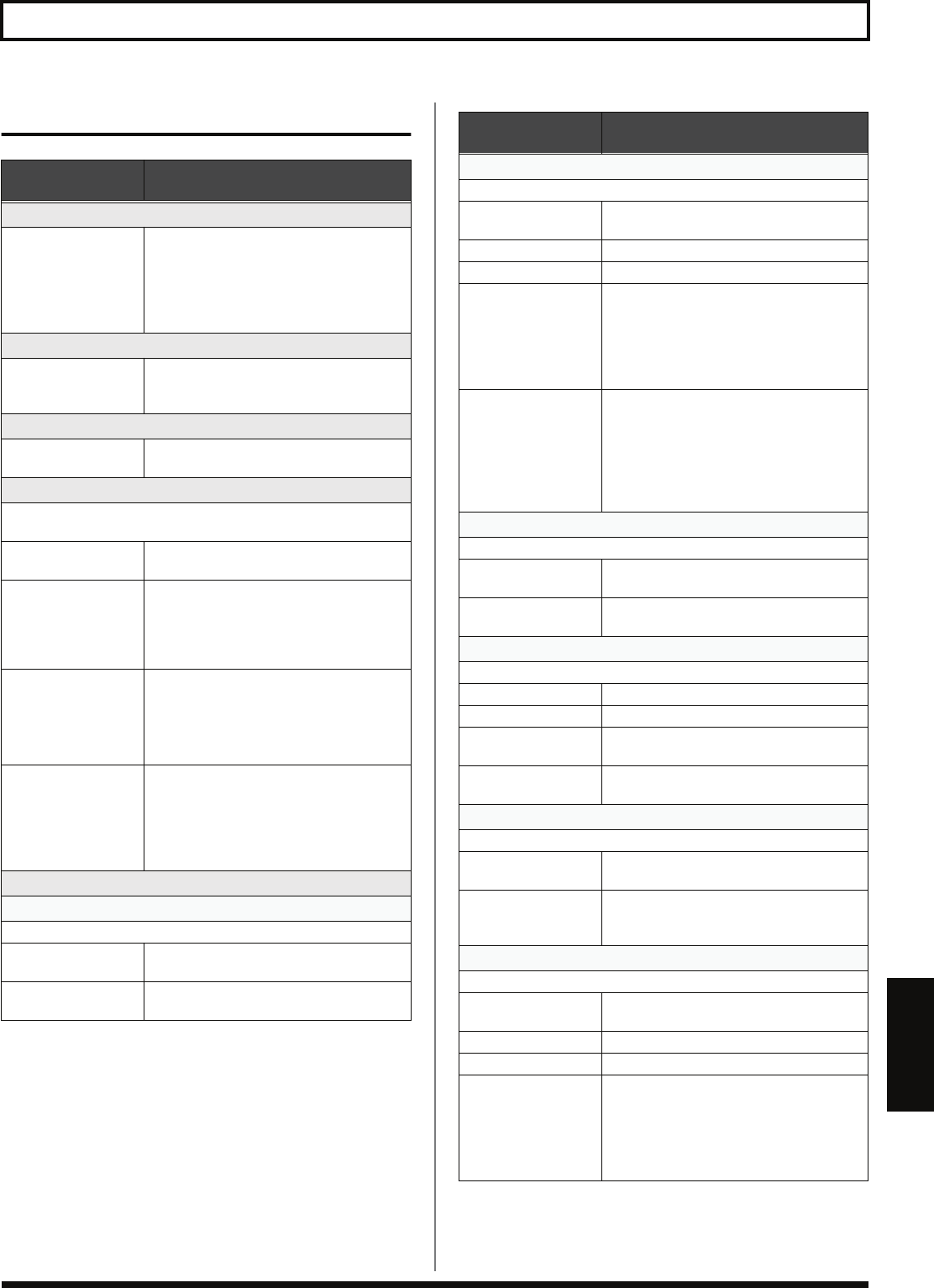
Parameter/
Range
Explanation
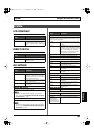
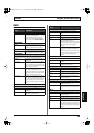
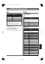
MIDI CH (MIDI Channel)
1–16ch
This sets the channel used for transmitting
and receiving MIDI messages.
When controlling another synthesizer
sound module using the BASS TO MIDI
function, also refer to
“BASS TO MIDI”
(p.
143).
OMNI MODE
OFF, ON
When MIDI OMNI MODE is set to ON,
messages are received on all MIDI channels,
regardless of the MIDI channel settings.
DEVICE ID
1–32
This sets the Device ID used for transmis-
sion and reception of Exclusive messages.
SYNC CLOCK
This setting determines the basis used for synchronizing the timing
for effect modulation rates and other time-based parameters.
INTERNAL Operations are synchronized to the VB-99’s
internal Clock.
AUTO (USB) Operations are synchronized to the MIDI
Clock received via USB. However, opera-
tions are automatically synchronized to the
VB-99’s internal Clock if the VB-99 is unable
to receive the external Clock.
AUTO (MIDI) Operations are synchronized to the MIDI
Clock received via MIDI. However,
operations are automatically synchronized
to the VB-99’s internal Clock if the VB-99 is
unable to receive the external Clock.
AUTO (RRC2) Operations are synchronized to the MIDI
Clock received via the RRC2 IN connector.
However, operations are automatically syn-
chronized to the VB-99’s internal Clock if
the VB-99 is unable to receive the external
Clock.
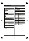
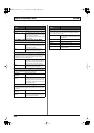
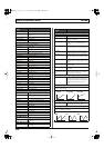
ROUTING
MIDI IN
→
This sets the routing of signals arriving at the MIDI IN connector.
OFF Only VB-99 Exclusive messages are received
via MIDI IN.
MAIN Signals received at MIDI IN are transmitted
to the VB-99’s internal section.
Parameter/
Range
Explanation
MIDI OUT
←
This sets the routing of signals at the MIDI OUT connector.
OFF Only Bulk Dump data is output from MIDI
OUT.
MAIN Signals from the VB-99 are output.
USB MIDI signals received via USB are output.
MIDI The MIDI signals received at MIDI IN are
output from MIDI OUT (thru).
When other signals also are set to be output
simultaneously from MIDI OUT, the signals
are mixed and then output together
(merge).
RRC2 The MIDI signals received at through RRC2
IN connector are output from MIDI OUT
(thru).
When other signals also are set to be output
simultaneously from MIDI OUT, the signals
are mixed and then output together
(merge).
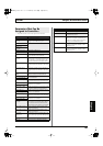
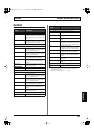
USB (MIDI)
→
This sets the routing of signals received via USB.
OFF Only VB-99 Exclusive messages are received
via USB.
MAIN Signals received via USB are transmitted to
the VB-99’s internal section.
USB (MIDI)
←
This sets the routing of signals output from the USB connector.
OFF Only Bulk Dump data is output from USB.
MAIN MIDI signals from the VB-99 are output.
MIDI MIDI signals received at MIDI IN are out-
put.
RRC2 MIDI signals received through RRC2 IN
connector are output.
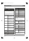
RRC2
→
This sets the routing of signals received via RRC2 IN connector.
OFF Only VB-99 Exclusive messages are received
via RRC2 IN connector.
MAIN Signals received at the RRC2 IN connector
are transmitted to the VB-99’s internal sec-
tion.
RRC2
←
This sets the routing of signals output from the RRC2 IN connector.
OFF Only Bulk Dump data is output from the
RRC2 IN connector.
MAIN MIDI signals from the VB-99 are output.
USB MIDI signals received via USB are output.
MIDI MIDI signals received at MIDI IN are output
from the RRC2 IN connector (thru). When
other signals also are set to be output simul-
taneously from the RRC2 IN connector, the
signals are mixed and then output together
(merge).
VB-99_e.book 149 ページ 2008年8月18日 月曜日 午後1時10分