


14
Notes
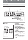
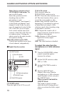
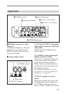
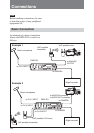
• Be sure not to connect devices other
than a UHF portable tuner.
• The unit outputs the power, only
when the unit operates with an
external power supply.
This connector outputs the power by
dividing the power input via the
DC IN 10-15 V connector. Thus the
output voltage depends on the power
input via the DC IN 10 - 15 V
connector.
3 INPUT (analog signal input)
connectors (XLR type 3-pin, female)
Input the analog audio signals of the
four channels CH1, CH2, CH3 and
CH4.
4 LINE/MIC/MIC +48V switch
Selects the position to match the
incoming signal level of each channel.
LINE: Set to this position when
connecting equipment with an
input signal level between
+10 dBu and –30 dBu.
MIC: Set to this position when
connecting the equipment with an
input signal between –30 dBu and
–70 dBu, especially when
connecting a microphone.
MIC +48V: Set to this position when
connecting the equipment with an
input signal between –30 dBu and
–70 dBu, especially when
connecting a DC +48V power
microphone.
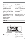
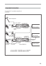
5 CASCADE IN (Cascade signal
input) connector (Phono jack)
Used for a cascade connection. When
this unit is as the second one
connected, connect this connector to
the COAXIAL connector located on
the right panel of the first DMX-P01.
This unit is synchronized with the first
DMX-P01 using the master clock
signal extracted from the signal of this
connector.
Note
In a cascade connection, the sampling
rate of both DMX-P01 mixers must be
matched. Set the sampling rate to
match using the SAMPLING RATE
switch.
Also, do not input the IEC60958
format signal to the CASCADE
INPUT connector.
Location and Function of Parts and Controls