


16
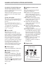
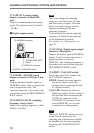
4 TAPE OUT (analog signal
output) connector (3.5mm TRS
jack)
Outputs an unbalanced stereo analog
signal. The reference level is fixed to
–10 dBu.
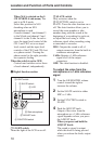
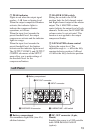
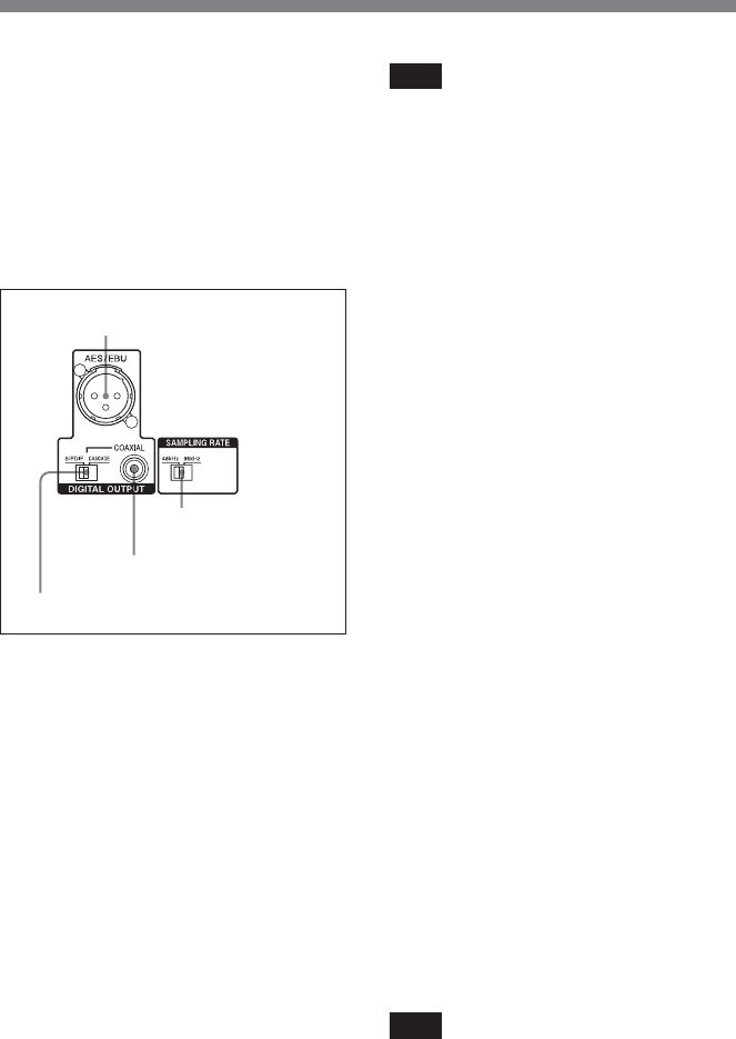
3 Digital output section
1 AES/EBU (AES/EBU signal
output) connector (XLR type 3-pin,
male)
Outputs the digital master signal in
AES/EBU format. Used to connect the
unit to a digital recorder. The
sampling frequency is the same as the
one selected using the 2 SAMPLING
RATE switch.
2 SAMPLING RATE (sampling
frequency select) switch
Selects the sampling frequency, either
48 kHz or 96 kHz.
1 AES/EBU connector
2 SAMPLING RATE
switch
3 COAXIAL connector
4 S/PDIF / CASCADE switch
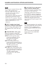
Note
When you change the sampling
frequency, turn the power off once,
and then turn it on again. After the
power is turned on again, the unit
operates according to the new
sampling frequency.
You can check the current sampling
frequency at which the unit operates
on the Information window.
For details, see “Information” on
page 21.
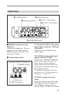
3 COAXIAL (digital signal output)
connector (Phono jack)
Outputs the digital signal in IEC60958
format. Used to connect the unit to a
digital recorder or a second
DMX-P01. The sampling frequency is
the same as the one selected using the
2 SAMPLING RATE switch.
4 S/PDIF / CASCADE switch
Selects the signal to be output from
the COAXIAL connector.
S/PDIF: Outputs the same signal as
the master output. Set to this
position when connecting the unit
to a digital recorder
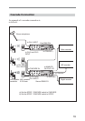
CASCADE: Outputs the Left and
Right bus signals. Set the switch to
this position when connecting the
COAXIAL connector to the
CASCADE IN connector of the
second DMX-P01 in a cascade
connection for adding inputs.
Note
When two DMX-P01 mixers are used
in the cascade connection, the
sampling rate of both mixers should
be matched. Set the same sampling
rate using the SAMPLING RATE
switch.
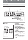
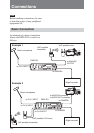
Location and Function of Parts and Controls