


15
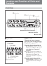
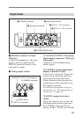
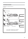
Right Panel
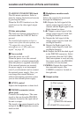
1 PHONES connector
2 Analog output section
3 Digital output section
4 DC IN 10 - 15V connector
6 STEREO/MONO switch
5 DC IN 10 - 15V connector
1 PHONES connector (3.5 mm
TRS jack)
Connects the headphones. The same
signal as the one output from the
PHONES connector located on the
front panel is output.
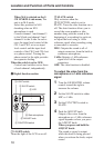
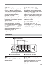
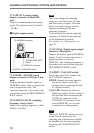
2 Analog output section
1 ANALOG OUTPUT L/R connectors
2 CAMERA connector
3 LEVEL switch
4 TAPE OUT connector
1 ANALOG OUTPUT L/R (analog
signal output) connectors (XLR type
3-pin, male)
Outputs the Left and Right analog
master signals.
2 CAMERA (analog signal input/
output) connector (12-pin)
Connects to a camcorder. Outputs the
master analog signal and inputs the
return signal from the camcorder.
Make connection which matches the
specifications of the camcorder using
the supplied connector.
For detailed information on the pin
assignment, see “Pin Assignments of
Connectors” on page 44.
3 LEVEL (output level select)
switch
Selects the reference level of the Left
and Right analog master signals and
the CAMERA output signal from
among +4 dBu, –20 dBu, and –60 dBu.