


In FPGA designs with multiple clock domains asynchronous FIFOs have to be used for
transferring data from one clock domain to the other and comprehensive control signals
have to be resynchronized.
Other clock sources can be added internally by using Spartan-6
TM
onchip digital clock
managers (DCMs) or PLLs or externally by connecting clock sources to other FPGA global
clock inputs. A wide range of clock frequencies can be synthesized with DCMs and PLLs.
For further details on DCMs/PLLs please see “Spartan-6
TM
FPGA Clocking Resources
User Guide UG382”.
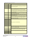
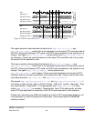
FX-2/FPGA slave FIFO connection
Only the logical behavior of slave FIFO interface is discussed here. For information about
the timing behavior like setup- and hold-times please see FX-2 datasheet.
All flags and control signals are active low (postfix “#”). The whole interface is synchronous
to IFCLK. The asynchronous FIFO transfer mode is not supported.
• SLWR#: FX-2 input, FIFO write-strobe
• SLRD#: FX-2 input, FIFO read-strobe
• SLOE#: FX-2 input, output-enable, activates FX-2 data bus drivers
• PKTEND#: FX-2 input, packet end control signal, causes FX-2 to send data to host at
once, ignoring 512 byte alignment (so called “short packet”)
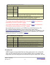
• Short packets sometimes lead to unpredictable behavior at host side. So CESYS USB
cards do not support short packets! This signal has to be statically set to HIGH! Dummy
data should be added instead of creating short packets. There is normally no lack of
performance by doing this, because transmission of USB packets is bound to a time
framing scheme, regardless of amount of payload data.
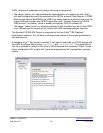
• FIFOADR[1:0]: FX-2 input, endpoint buffer addresses, CESYS USB cards use only two
endpoints EP2 (OUT, ADR[1:0] = b”00”) and EP6 (IN, ADR[1:0] = b”10”)
• Switching FIFOADR[1] is enough to select data direction. FIFOADR[0] has to be
statically set to LOW!
• FLAG#-A/-B/-C: FX-2 outputs, A => EP2 “empty” flag, B => EP2 “almost empty” flag,
meaning one 16 bit data word is available, C => EP6 “almost full” flag, meaning one 16
bit data word can still be transmitted to EP6, there is no real “full” flag for EP6, “almost
full” could be used instead
• FD[15:0]: bidirectional tristate data bus
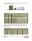
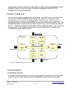
Introduction to example FPGA designs
The CESYS USBS6 Card is shipped with some demonstration FPGA designs to give you
an easy starting point for own development projects. The whole source code is written in
USBS6 / C1030-5510 http://www.cesys.com/
User Doc V0.3 -18- preliminary