


incremented automatically in block transfers. You can find details on enabling/disabling the
burst mode and address auto-increment mode in the CESYS application note “Transfer
Protocol for CESYS USB products” and software API documentation.
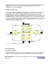
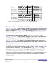
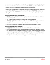
CESYS USB transfer protocol is converted into one or more WISHBONE data transaction
cycles. So the FX-2 becomes a master device in the internal WISHBONE architecture.
Input signals for the WISHBONE master are labeled with the postfix “_I”, output signals
with “_O”.
WISHBONE signals driven by the master:
• STB_O: strobe, qualifier for the other output signals of the master, indicates valid data
and control signals
• WE_O: write enable, indicates, if a write or read cycle is in progress
• ADR_O[31:2]: 32-Bit address bus, the software uses BYTE addressing, but all internal
WISHBONE accesses are DWORD (32-Bit) aligned. So address LSBs [1:0] are
discarded.
• DAT_O[31:0]: 32-Bit data out bus for data transportation from master to slaves
WISHBONE signals driven by slaves:
• DAT_I[31:0]: 32-Bit data in bus for data transportation from slaves to master
• ACK_I: handshake signal, slave devices indicate a successful data transfer for writing
and valid data on bus for reading by asserting this signal, slaves can insert wait states by
delaying this signal, it is possible to assert ACK_I in first clock cycle of STB_O assertion
using a combinatorial handshake to transfer data in one clock cycle (recommendation:
registered feedback handshake should be used in applications, where maximum data
throughput is not needed, because timing specs are easier to meet)
USBS6 / C1030-5510 http://www.cesys.com/
User Doc V0.3 -26- preliminary