


10
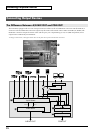
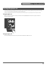
Names of Things and What They Do
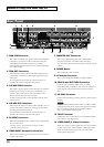
1. PGM PVW Connector
This outputs the DSK preview picture. Before performing DSK
composition, you connect a monitor to check and verify the
video displayed as the DSK foreground. You can then
composite the background picture after first checking the logos,
text, or other images.
2. PGM OUT Connectors
These output the mixed video plus the DSK composition. You
connect them to projectors or other display equipment for the
final output.
Two composite connectors and one S-Video connector are
available. All connectors output the same picture.
3. A/B MIX PVW Connector
This outputs a preview picture for the video mix. You connect a
monitor for previewing a source prior to committing to a
transition. The current location of the video fader and the
selected video on the inactive bus are output.
A variety of setting menus are also displayed at the top of the
preview picture.
4. A/B MIX OUT Connectors
These output only the mix results for A Bus and B Bus. You can
connect a video deck or other such recording unit and record
the video prior to DSK composition.
Two composite connectors and one S-Video connector are
available. All connectors output the same picture.
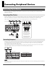
5. PC INPUT Connectors
These are for RGB-signal input. You can connect computers that
serve as video source.
*Incoming computer signal will be downscalled to match the
resolution of other video sources.
6. VIDEO INPUT (Composite) Connectors
These are for composite-signal input. You can connect cameras
or other video sources.
7. MONITOR OUT Connectors
These output signals being input via the VIDEO INPUT
connectors (composite or S-Video) without processing.
You can connect a monitor to each of these “loop-thru
"
monitor
outputs.
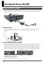
8. POWER Button
This switches the power on and off.
9. AC Adapter Connector
This is for connecting the included AC adapter (PSB-7U).
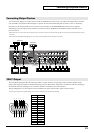
10. MIDI IN and OUT/THRU Connectors
Use these when connecting a MIDI device (a V-LINK-
compatible product or the like) to operate the unit remotely, or
when using the unit to perform remote control of another
device.
11. RS-232C Connector
Use this when connecting an external device to operate the unit
remotely.
For more information about remote control via MIDI, V-LINK,
or RS-232C interface, please download the separately available
reference materials from the following Roland website.
http://www.rolandsystemsgroup.net/
12. TALLY Connector
Provides low-current contact closure to activate tally lamps on
your cameras or tally light system.
13. VIDEO INPUT (S-Video) Connectors
These are for input of S-Video signals. You can connect cameras
or other video sources. When composite or RGB and S-Video
signals are simultaneously input to the same channel, the
S-Video signals take priority.
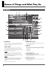
Rear Panel
241
3
8
9
10
5 6
7
11 12
13