


14
Names of Things and What They Do
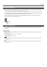
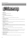
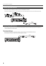
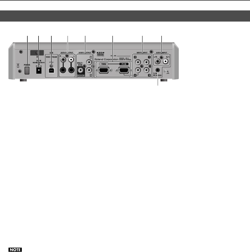
fig.rear-panel.eps
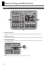
1. POWER Button
This switches the power to the VR-3 on and off.
2. DC IN Connector
This is for connecting the included AC adapter.
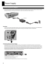
* Use the cord hook to secure the AC adapter cord in place (p. 8).
3. USB Port
You can use this to output the results of video and audio mixing on the VR-3 to a computer.
4. AUDIO OUTPUT Connectors
These output the results of audio mixing. Connect output equipment (an amplifier or speakers) and recording equipment (such
as a video recorder).
5. VIDEO OUTPUT Connectors
These output the results of video mixing. Connect output equipment (such as a projector) and recording equipment (such as a
video recorder).
The PREVIEW connector is for connecting a preview monitor.
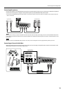
6. PC IN and THRU Connectors
You can connect RGB output from a computer to the PC IN connector and input logos, text, or still images. Input made via this
connector is assigned to channel 4. When composite input and RGB input are made to channel 4 at the same time, the RGB input
takes priority.
The THRU connector is for connecting a computer monitor.
Small text from a computer may not be shown clearly on the final output. If you input text, the font size should be big enough.
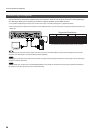
7. VIDEO INPUT Connectors
Use these to connect video cameras or other video sources. When composite input and RGB input are made to channel 4 at the
same time, the RGB input takes priority.
* You can use the menus to lock the channel-4 input to composite or RGB. Go to the [SYSTEM] menu and select [PC IN], then use [CH4 INPUT
SOURCE] to select [PC IN] or [VIDEO]. Refer to “Menu Operations” (p. 44) and “SYSTEM Menu” (p. 47).
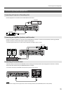
8. AUDIO INPUT Connectors
These are for connecting the audio output of video players or other source equipment. Input made via the RCA connectors is
assigned to channels 5/6.
9. PC AUDIO Connector
This is for connecting audio output from a computer. Input from the computer is assigned to channels 7/8.
Rear Panel
1 2 34 5 6 7 8
9