


NETWORK SET SETTING
8
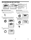
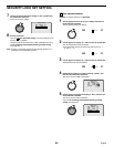
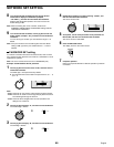
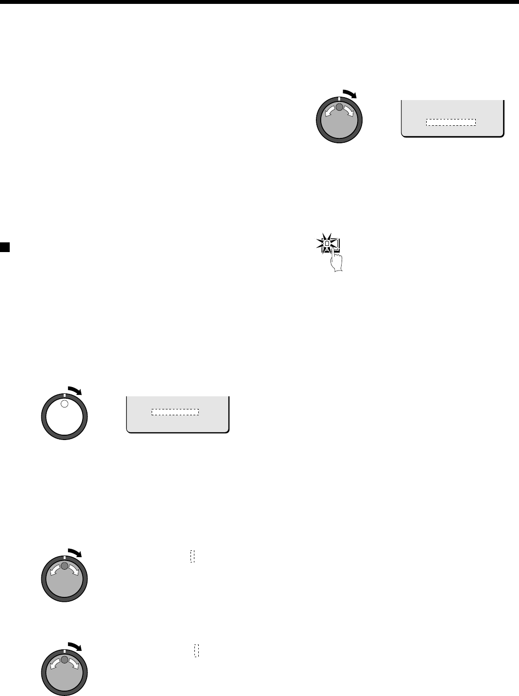
Turn the shuttle dial clockwise and use the jog dial and
shuttle dial to display the GATEWAY (example:
“ 192.168.0.1” ), and then turn the shuttle dial clockwise.
With the final shuttle dial operation, the cursor moves to the
PORT setting of “80”.
Note: When connecting this unit to a network, check the IP
ADDRESS, SUBNET MASK and GATEWAY settings with the
LAN Network Administrator.
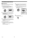
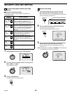
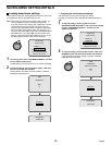
9
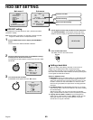
Turn the shuttle dial clockwise, use the jog dial to enter the
PORT number (example: “ 90"), and then turn the shuttle dial
clockwise.
You can set any port number you wish within the range of 1 to
65535.
Note: If the port number is set to something other than the default
setting of “80”, type in the port number after the “:” in the IP
address.
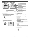
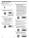
PASSWORD SET setting
For network connection there are three access levels, each of which
has a password. Each password can consist of a combination of 4 to 8
alphanumeric symbols.
Note: The cursor cannot be moved to ID or PASSWORD (4-8).
Example: Set AB123456 as the ID1 password.
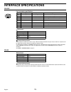
1
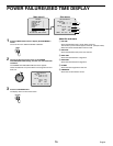
Use the jog dial to move the cursor to ID1, and then turn the
shuttle dial clockwise.
The initial digit 1 of the password entry flashes.
•
The characters that can be used in the password are: 0, 1 ... 9,
A, B ... Z
Note:
•
ID1: This level can only observe a live image through the network.
•
ID2: This level can observe a live image and play back and search
recorded images through the network.
•
ID3: This level allows all digital video recorder operations and
settings to be carried out.
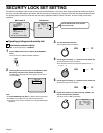
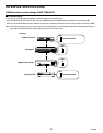
2
Use the jog dial to display “ A” , and then turn the shuttle dial.
The second digit 1 flashes.
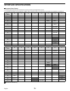
3
Use the jog dial to display “ B” , and then turn the shuttle dial.
The third digit 1 flashes.
4
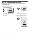
Repeat this procedure to continue entering “ 123456” , and
then turn the shuttle dial clockwise.
The cursor moves to ID2.
5
As required, use the same procedure to set passwords for
ID2 and ID3, and then turn the shuttle dial clockwise.
The cursor moves to LAN CARD.
6
Press the EXIT/OSD button.
The display returns to the normal screen.
7
Computer operation
Refer to the separate Manual for Remote Operation by Network
Connection.
PORT : 00080
ID : PASSWORD (4-8)
ID1 : 1111----
ID2 : 2222----
ID3 : 3333----
ID1 : A111----
ID1 : AB11----
PORT : 00080
ID : PASSWORD (4-8)
ID1 : AB123456
ID2 : 2222----
ID3 : 3333----
EXIT/OSD
68
English