


Rear Panel 21
D24—Owner’s Manual
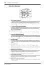
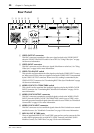
H SCSI port
This 50-pin, half-pitch SCSI connector is used to connect external SCSI disk drives and
removable media drives for additional recording space. The SCSI interface supports
Narrow SCSI-2 (FAST-20). A personal computer equipped with SCSI can also be con-
nected, which can then access files on the MO disk in the D24. See “SCSI & the D24”
on page 154 for more information.
I SERIAL I/O port
This 9-pin D-sub connector is used to connect the D24 to a video remote controller or
video editor for control using 9-pin protocols. See “Connecting a Video Editor” on page
151 for more information.
J SYNC OUT port
This 15-pin D-sub connector is used to connect multiple D24s in a synchronized sys-
tem. In addition to various control signals, SYNC connections also carry wordclock
and timecode signals. See “Expanding the Number of Tracks” on page 145 for more
information.
K REMOTE IN/SYNC IN port
This 15-pin D-sub connector is used to connect multiple D24s in a synchronized sys-
tem. It can also be used to connect an optional remote controller. In addition to various
control signals, SYNC connections also carry wordclock and timecode signals. See
“Expanding the Number of Tracks” on page 145 for more information.
L Cooling fan
The cooling fan keeps the internal components cool. See “Installing the D24” on page
3 for more information.
M AC IN connector
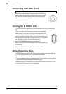
This connector is used to connect the D24 to an AC outlet, using the supplied power
cord. See “Connecting the Power Cord” on page 24 for more information.
N TIMECODE OUTPUT connector
This male XLR-3-32 connector (balanced) transmits internally generated SMPTE/EBU
timecode when the D24 is used as the timecode master, or the timecode received at
TIMECODE INPUT when the D24 is used as a timecode slave. See “Timecode Connec-
tions” on page 134 for more information.
O TIMECODE INPUT connector
This female XLR-3-31 connector (balanced) receives SMPTE/EBU timecode when the
D24 is used as a timecode slave. See “Timecode Connections” on page 134 for more
information.
P COAXIAL STEREO DIGITAL OUTPUT connector
This phono jack transmits S/PDIF format, 2-channel digital audio. See “Using the
Coaxial Digital Input & Output” on page 187 for more information.
Q COAXIAL STEREO DIGITAL INPUT connector
This phono jack receives S/PDIF format, 2-channel digital audio. See “Using the Coax-
ial Digital Input & Output” on page 187 for more information.
R SLOTs 1–4
These four slots are for use with optional mini YGDAI cards, which offer various analog
and digital I/O options. See “Digital Audio I/O” on page 181 for more information.