


73
Reference
*26
With the “sort” and “thru” settings, the order
in which notes are played back will depend on
the Arpeggio sequence data.
*27
If the Arpeggio Category is set to Ct, you will
not hear any sounds unless you select “direct”
here.
*28
original
The Arpeggio plays back at the preset
velocities.
thru
The Arpeggio plays back according to the
velocity values received. In other words, high
velocity values increase the volume of
Arpeggio playback.
*29
You can also create a lower and an upper
trigger range for the Arpeggio, with a “hole”
in the middle, by specifying the highest note
first. For example, setting a Note Limit of “C5-
C4” lets you trigger the Arpeggio by playing
notes in the two ranges of C -2 to C4 and C5
to G8; notes played between C4 and C5 have
no effect on the Arpeggio.
*30
The Velocity/Gate Time cannot be decreased
beyond its normal minimum of 1; any values
outside that range will automatically be
limited to the minimum.
*31
The Velocity cannot be decreased or increased
beyond its normal range of 1 to 127; any
values outside that range will automatically
be limited to the minimum or maximum.
*32
You can set the parameters related Voice only
when entering the Utility mode from the
Voice mode.
*33
This parameter’s function varies according to
the selected Filter Type. If the selected filter is
an LPF, HPF, BPF (excluding the BPFw), or
BEF, this parameter is used to set the
Resonance. For the BPFw, it is used to adjust
the Width of the band.
*34
This parameter is available for the LPF when
the filter used by the part is a combination
type of LPF and HPF (Multi Part Edit).
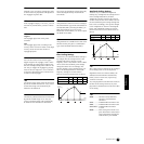
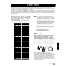
*35
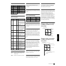
Filter Scaling Settings
The best way to understand Filter Scaling is
by example. For the settings shown in the
example table below, the basic Cutoff
frequency value is 64, and the various Offset
values at the selected Break point settings
change that basic value accordingly. The
specific changes to the Cutoff frequency are
shown in the diagram below. The Cutoff
frequency changes in a linear fashion
between successive Break Points as shown.
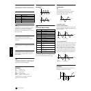
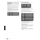
*36
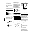
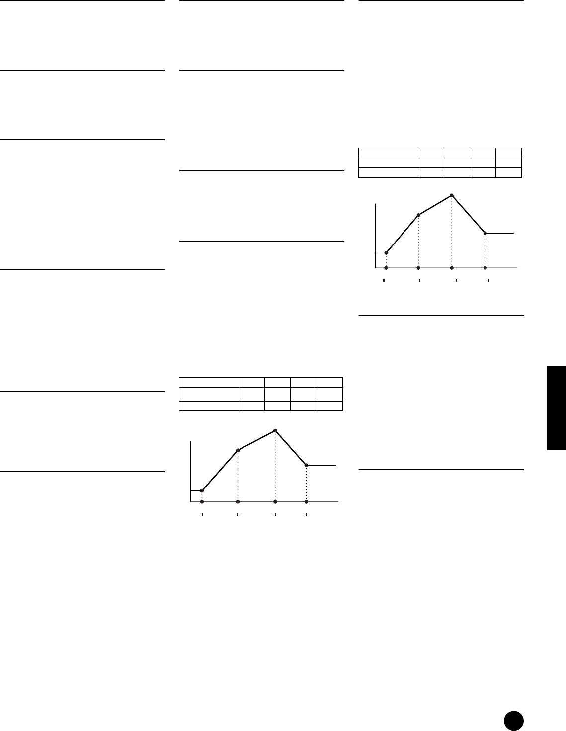
Amplitude Scaling Settings
The best way to understand Amplitude
Scaling is by example. For the settings shown
in the example table below, the basic
Amplitude (volume) value for the selected
element is 80, and the various Offset values at
the selected Break point settings change that
basic value accordingly. The specific changes
to the Amplitude are shown in the diagram
below. The Amplitude changes in a linear
fashion between successive Break Points as
shown.
*37
BP1 to BP4 will be automatically be arranged
in ascending order across the keyboard.
Regardless of the size of these Offsets, the
minimum and maximum Cutoff/Volume
limits (values of 0 and 127, respectively)
cannot be exceeded.
Any note played below the BP1 note results in
the BP1 Level setting. Likewise, any note
played above the BP4 note results in the BP4
Level setting.
*38
L&R..............OUTPUT L&R, DIGITAL
OUTPUT, and OPTICAL
OUTPUT
as12 ..............ASSIGNABLE OUTPUT 1&2
as34 ..............ASSIGNABLE OUTPUT 3&4
as1/2/3/4.....ASSIGNABLE OUTPUT
1/2/3/4
drum.............This setting is for Drum voice
parts. When this is selected, the
output destination settings for
each Drum key are enabled.
1234
BREAKPOINT
C
1D
2C3
A4
OFFSET -4 +10 +17 +4
C 1
D 2
60
74
81
68
Break Point 1 Break Point 2 Break Point 3 Break Point 4
A4C3
Note
Cutoff
Frequency
1234
BREAKPOINT C1 C2 C3 C4
OFFSET -4 +10 +17 +4
76
90
97
84
Note
Amplitude
C1
Break Point 1 Break Point 2 Break Point 3 Break Point 4
C4C3C2
Function List