


Selecting and Creating Tones
E-27
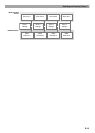
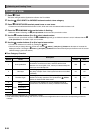
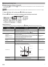
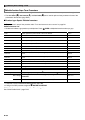
■ Block (7): Total Block Filter Editable Parameters
Preparation
On the screen that appears in step 2 under “To edit and save a tone as a user tone” (page E-21), select “Total Filter >Ent” and then
press
bq
ENTER to enter the group.
Editable Parameter List
• Shaded cells indicate a group made up of multiple items. Press
bq
ENTER to display the items that make up a group.
• (V) at the end of a display item indicates an item that can be selected as a Block (10) virtual controller destination (page E-29).
PortaTime (V)
Portamento Time. Specifies the time until the next note is reached by
Portamento.
0 to 127
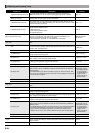
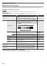
Display Text Description Settings
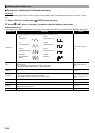
FilterType
Filter type. Selects the filter type.
LPF: Low-pass filter. Cuts high-range components above the cut off frequency.
BPF: Band-pass filter. Cuts low-range and high-range components outside of a range centered on
the cut off frequency.
HPF: High-pass filter. Cuts low-range components below the cut off frequency.
Refer to the cell to the
left.
Cutoff (V) Cutoff frequency. Specifies the cut off frequency of all Solo Synthesizer tones. 0 to 127
Resonance (V) Resonance. Emphasizes notes in the vicinity of the cut off frequency to alter the tone. 0 to 127
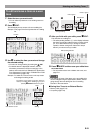
TouchSense (V)
Touch sense. Specifies the degree of change in the filter in accordance with change in keyboard
playing touch.
–64 to 0 to +63
KeyFollow (V)
Key follow. Adjusts the amount of filter change between neighboring keyboard keys. A higher value
represents greater change.
–128 to 0 to +127
KeyFolBase (V)
Key follow base. Keyboard key that is the center of key follow.
• Setting can be specified using the keyboard keys.
C-1 to G9
Env.Retrig
Envelope generator retrigger. Turning on this setting retriggers the filter with each keyboard key
press.
Off, On
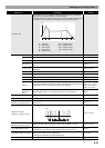
Env.Depth (V) Envelope depth. Specifies how the envelope shown below is applied. –64 to 0 to +63
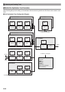
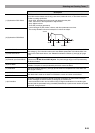
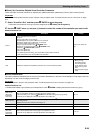
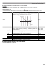
Envelope >Ent
Total filter envelope. Group of editable envelope (Envelope Generator) parameters applied to Total
Block filters.
• For details about group items, see “Pitch Envelope”. With this group, the vertical (Level) axis in the
pitch envelope diagram corresponds to how the filter is applied.
0 to 127 (Initial Level to
Release Level 2)
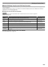
• The setting ranges for
Clock Trigger and
External Input Trigger
are the same as those
for Pitch Envelope.
LFO1 Depth (V) LFO1 depth. Specifies how LFO1 from Block (8) is applied. –64 to 0 to +63
LFO2 Depth (V) LFO2 depth. Specifies how LFO2 from Block (9) is applied. –64 to 0 to +63
Display Text Description Settings