


Reference
E-90
14: Lo-Fi
Applies various types of noise to the input signal to reproduce
a retro Lo-Fi sound.
Includes wow and flutter for rotational fluctuation like that in
tapes and records, a Noise 1 generator that generates
continual FM radio type, and a Noise 2 generator that
generates record play types scratch noise.
Parameters and Value Ranges:
1 :Wow and Flutter Rate (0 to 127)
Adjusts the wow and flutter rate.
2 :Wow and Flutter Depth (0 to 127)
Adjusts the wow and flutter depth.
3 :Noise1 Level (0, 1, 2, 3, 4, 5) (Param A)
Adjusts the level of Noise Generator 1.
4 :Noise2 Level (0, 1, 2, 3, 4, 5) (Param B)
Adjusts the level of Noise Generator 2.
5 :Noise2 Density (0, 1, 2, 3, 4, 5)
Adjusts the frequency of Noise Generator 2.
6 :Bit (0, 1, 2, 3)
Distorts the sound. A larger number produces greater
distortion.
Important!
Raising the noise level while a note is not sounding will cause
noise to sound, even if there is no input signal.
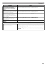
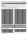
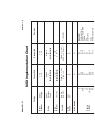
■ Normal DSP Dual Type DSP Parameters
Dual type DSPs are configured by combining two different
single type DSPs. Use the procedure below to determine what
parameters that can be configured for each dual type DSP,
and the operation, and setting ranges of dual type DSPs.
Example: Type number 29: Distortion-Wah
1. The DSP type name has two parts: a left side part and a
right side part.
Distortion-Wah 3 “Distortion” and “Wah”
2. Find out what parameters you can configure by looking up
the left side part of a dual type DSP in the “Type Name”
column of the table below.
3. Find the same type names in the table under “Normal DSP
Single Type DSP Parameters” on pages E-88 through
E-90, and note the operation and setting ranges of the
items that are the same as those shown in the
“Configurable Parameters” column of the above table.
4. Next, repeat steps 2 and 3 above for the right side part of
the dual type DSP parameter name.
• (Param) in the table under step 2 of this procedure are
parameters assigned to the
5
8/16 and MASTER sliders
when Hex Layer tones are selected. The (Param) of the
single type DSP whose name is on the left is assigned the
5
8/16 button, while the single type DSP whose name is
on the right is assigned the
5
MASTER button.
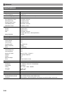
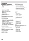
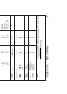
■ Solo Synthesizer DSP Parameters
• (Param A) and (Param B) are parameters assigned to the
5
8/16 and MASTER sliders when Solo Synthesizer
tones are selected.
(No number): Bypass
Selecting this option disables application of DSP.
No parameters
01: Auto Pan
Parameters and Ranges
1 :LFO Waveform (Range: sin, tri)
2 :LFO Rate (Range: 0 to 127) (Param A)
3 :LFO Depth (Range: 0 to 127) (Param B)
4 :Manual (Range: –64 to 0 to 63)
02: Distortion
Parameters and Ranges:
1 :Gain (Range: 0 to 127) (Param A)
2 :Level (Range: 0 to 127) (Param B)
03: Flanger
Parameters and Ranges
1 :LFO Waveform (Range: sin, tri, random)
2 :LFO Rate (Range: 0 to 127) (Param A)
3 :LFO Depth (Range: 0 to 127) (Param B)
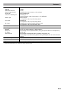
Type Name Configurable Parameters
Wah LFO Waveform
LFO Rate
LFO Depth (Param)
Distortion Gain (Param)
Level
Chorus LFO Waveform
LFO Rate (Param)
LFO Depth
Flanger LFO Waveform
LFO Rate (Param)
LFO Depth
Reflection Feedback (Param)
Compressor Threshold (Param)
Level
Auto Pan LFO Waveform
LFO Rate
LFO Depth
Manual (Param)
Tremolo LFO Waveform
LFO Rate (Param)
LFO Depth
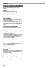
• In our “Distortion-Wah” example, the left side part of the
name is “Distortion” so we can see in the above table
that “Gain” and “Level” parameters can be configured.
You can find out about the operations and setting ranges
of “Gain” and “Level” by referring to “03: Distortion” on
page E-88.
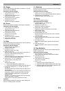
• The parameter numbers that appear on the parameter
setting screen start from 1, and the number is
incremented for each successive parameter.
The parameter numbers of our “Distortion-Wah” example
would be as shown below.
1: Gain
2: Level
3: LFO Waveform
4: LFO Rate
5: LFO Depth