


LS9 Editor Owner’s Manual
53
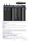
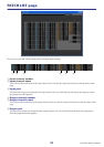
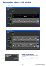
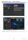
A Mount
Select a GEQ module or effect module for mounting in the rack, from the following choices.
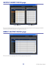
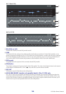
B Input patch
Select the input port(s) that will be assigned to the rack, from the following choices.
(*)
Selectable only for effect modules.
This is not shown if nothing is mounted in the rack.
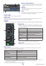
C Module graphic
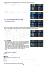
This area shows a graphic of the GEQ module or effect module that is currently assigned to the rack, and the
parameters of that module. You cannot edit the parameters in this screen.
Double-click this to open the module editor for that rack unit.
By holding down the <Ctrl>(< >) key of your computer keyboard and double-clicking this, you can open mul-
tiple rack module editors. For these additional editors, the rack select buttons are not linked with the RACK
popup window of the LS9-32 itself.
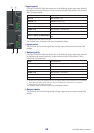
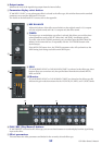
D Input meter/Output meter
These indicate the level of the signals being input and output from the rack.
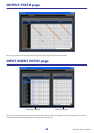
E Output patch
Select the output port(s) that will be assigned to the rack, from the following choices.
(*1)
INPUT CH 33–64 can be displayed only if you’re editing offline and have selected LS9-32 in the Model Select field of the Mixer Setup
window, or if you are editing online with the LS9-32 connected.
(*2)
Selectable only for effect modules.
F ON, BYPASS
This switches the GEQ module or effect module between active and bypassed states.
A GEQ module is active when the ON button is lit.
An effect module is active when the BYPASS button is dark.
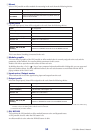
BLANK No assignment
31 Band GEQ 31-band 1-in/1-out graphic equalizer
Flex15GEQ
2-in/2-out graphic equalizer that allows any fifteen of the 31
bands to be controlled
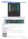
EFFECT Internal effect (only for RACK 5–8)
NONE No assignment
MIX1–16
(*)
MIX channel 1–16
MATRIX1-–8
(*)
MATRIX channel 1–8
ST L, ST R, MONO(C)
(*)
STEREO channel L/R, MONO channel
INS CH 1–32 INPUT CH 1–32 insert out
INS MIX 1–16 MIX channel 1–16 insert out
INS MATRIX1–8 MATRIX channel 1–8 insert out
INS ST L, INS ST R, INS
MONO(C)
Insert-out of STEREO channel L/R or the MONO channel
NONE No assignment
IN CH 1–64
(*1)(*2)
INPUT jacks 1–64
(*1)
STIN1L-STIN4R
(*2)
L/R channels of ST IN jacks 1–4
INS CH 1–32
INPUT CH 1–32 insert in
INS MIX 1–16 MIX channel 1–16 insert in
INS MTRX1–INS MTRX8 MATRIX channel 1–8 insert in
INS ST L, INS ST R, INS
MONO(C)
Insert-in of STEREO channel L/R or the MONO channel