


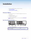

Front Panel Operation
DMP 64
DIGITAL MATRIX PROCESSOR
INPUTS
CLIP
SIGNAL
123 456
CONFIG
OUTPUTS
CLIP
SIGNAL
1234
bc da
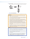
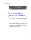
Figure 7. DMP64 Front Panel
a
Power LED — The power indicator lights when the DMP64 is operational.
b
Configuration connector — The USB 2.0 port uses a mini type-B connector to
connect to a host computer for control. The DMP64 USB driver must be installed
prior to using the port (see Install the USB Driver on page17).
The DMP64 appears as a USB peripheral with bi-directional communication. The
USB connection can be used for software operation (see Windows-based Program
Control on page15), and SIS control (see Software Control on page14).
c
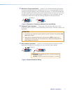
Input Indicators — Stacked red (signal clipping) and green (signal present) LEDs for
inputs 1 – 6 . Each column represents one input channel.
The green signal LED varies in brightness corresponding to the real-time input signal
level. It begins to light at – 60dBFS increasing in fifteen steps to full intensity as the
signal level increases. When the signal reaches – 3dBFS or above, the red clipping
LED lights and remains lit as long as the signal remains above – 3dBFS. When it falls
below that level, the red LED remains lit for 200 milliseconds, after which the display
resumes real-time monitoring of the signal level.
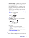
d
Output Indicators — Stacked red (signal clipping) and green (signal present) LEDs
for outputs 1 through 4. Each LED column represents one output channel.
The green signal LED varies in brightness corresponding to the output signal level. It
begins to light at – 60dBFS increasing to full intensity corresponding to signal level
increases. When the signal level reaches – 3dBFS or above, the red clipping LED
lights and remains lit as long as the signal remains above – 3dBFS. When it falls
below that level, the red LED remains lit for 200 milliseconds, after which the display
resumes real-time monitoring of the signal level.
DMP64 • Operation 10