


50
■ MIXER
This sets the output level of the carrier. The level you specify
here will be the input level to the band-pass filter of the car-
rier.
A: OSC 1 Level ❮ ❯ ..........................[000...127]
Specify the output level of OSC1 (carrier).
B: Inst Level ❮ ❯.................................[000...127]
Specify the output level of the signal that is input from the
AUDIO IN 1 jack.
C: Noise Level ❮ ❯ ...........................[000...127]
Specify the output level of the noise generator.
■ FILTER
These are the parameters for the band-pass filter of the car-
rier.
A: Formant Shift ❮ ❯ ...................[–2...+2]
This shifts the cutoff frequency of each band-pass filter of the
carrier, allowing you to dramatically modify the character of
the vocoder output.
B: Cutoff ❮ ❯ .................................[–63...+63]
This continuously shifts the cutoff frequency of each band-
pass filter of the carrier.
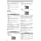
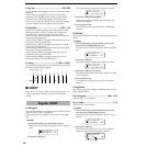
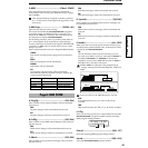
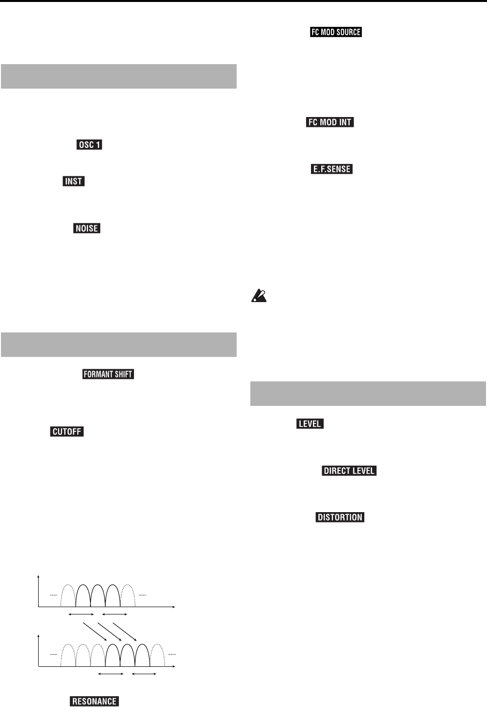
How “Formant Shift” and “Cutoff” are related
When “Formant Shift” = 0 and “Cutoff” = 0, the frequency
response will be as specified by the cutoff frequencies of
each band-pass filter of the modulator.
Adjustments to “Cutoff” will smoothly shift the frequency
response
The shift in frequency response caused by “Formant Shift”
is smoothly varied by “Cutoff” in two stages above and
two stages below (four stages above and below when used
in conjunction with “Formant Shift”).
C: Resonance ❮ ❯ ....................[000...127]
Specify the amount of resonance for each band-pass filter.
Increasing this value will emphasize the regions near each
cutoff frequency.
D: Mod Src ❮ ❯ .................[EG 1...MIDI 2]
Select the modulation source that will be applied to “Cut-
off.”
The selectable modulation sources are the same as for the
Virtual Patch modulation sources (Source) for synth parame-
ters.
Refer to p.42 “■ VIRTUAL PATCH.”
E: Mod Int ❮ ❯ ......................... [–63...+63]
Specify the depth of the modulation that will be applied to
“Cutoff.”
F: E.F.Sense ❮ ❯ .........................[000...127]
Specify the sensitivity of the envelope follower of the modu-
lator.
With low settings of this parameter, the rise and fall of the
signal from the AUDIO IN 2 jack will be detected rapidly.
With high settings of this parameter, the change will become
slower, producing a sound with no attack and a long release.
With a setting of 127, the response of the signal being input
at that time will be maintained. Subsequently, the sound will
be produced with the response that is being held, regardless
of whether or not there is any input.
If you set this to 127 when there is no input signal
present there will be no output even if an audio signal
is subsequently input.
■ AMP
A: Level ❮ ❯....................................[000...127]
Specify the volume level of the internal tone generator
(OSC1/NOISE) for the carrier.
B: Direct Level ❮ ❯ .................[000...127]
Specify the volume level of the audio that is output directly
from the AUDIO IN 2 jack.
C: Distortion ❮ ❯........................[ON, OFF]
If this is ON, distortion will be applied to the OSC1/NOISE/
AUDIO IN 1 signal.
D: Vel Sense............................................... [–63...+63]
Specify how velocity (keyboard playing dynamics) will
affect the volume.
With positive (+) settings, the volume will increase as you
play harder.
With negative (–) settings, the volume will decrease as you
play harder.
E: KBD Track............................................... [–63...+63]
Specify how keyboard tracking will affect the volume.
With positive (+) settings, the volume will increase as you
play above the C4 note on the keyboard, and will decrease as
you play below C4.
With negative (–) settings, the volume will decrease as you
play above the C4 note on the keyboard, and will increase as
you play below C4.
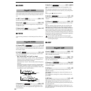
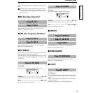
Page07: MIXER
Page08: FILTER
Cutoff (range in which BPF 8 will change)
0 +63-63
BPFBPFBPFBPF BPFBPF
BPFBPFBPFBPF BPFBPF
897
897
Frequency
Frequency
Formant Shift:+2
Cutoff (range in which BPF 8 will change)
0
+63
-63
Page09: AMP