


151
MIDI Implementation
Appendices
❍
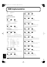
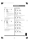
Data set 1DT1
This is the message that actually performs data transmission, and is used when you wish to
transmit the data.
Status
Data byte Status
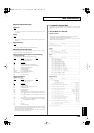
F0H 41H, dev, 00H, 43H, 12H, aaH, bbH, F7H
ccH, ddH, eeH, ... ffH, sum
Byte
Explanation
F0H Exclusive status
41H ID number (Roland)
dev Device ID (dev: 00H - 1FH, 7FH, Initial value is 10H)
00H Model ID #1 (RD-700)
43H Model ID #2 (RD-700)
12H Command ID (DT1)
aaH Address MSB: upper byte of the starting address of the data to be sent
bbH Address: upper middle byte of the starting address of the data to be
sent
ccH Address:lower middle byte of the starting address of the data to be
sent
ddH Address LSB: lower byte of the starting address of the data to be sent.
eeH Data: the actual data to be sent. Multiple bytes of data are transmitted
in order starting from the address.
: :
ffH Data
sum Checksum
F7H EOX (End Of Exclusive)
* The amount of data that can be transmitted at one time depends on the type of data, and
data will be transmitted from the specified starting address and size. Refer to the address
and size given in “Parameter Address Map” (p. 153).
* Data larger than 256 bytes will be divided into packets of 256 bytes or less, and each
packet will be sent at an interval of about 20 ms.
* Regarding the checksum, please refer to (p. 160)
* Not Received when the GM Mode is ON.
❍
Data set 1DT1 (GM Mode)
Status Data byte Status
F0H 41H, dev, 42H, 12H, aaH, bbH, ccH, F7H
ddH, ... eeH, sum
Byte Explanation
F0H Exclusive status
41H ID number (Roland)
dev Device ID (dev: 10H)
42H Model ID (GS)
12H Command ID (DT1)
aaH Address MSB: upper byte of the starting address of the transmitted
data
bbH Address: middle byte of the starting address of the transmitted data
ccH Address LSB: lower byte of the starting address of the transmitted
data
ddH Data: the actual data to be transmitted. Multiple bytes of data are
transmitted starting from the address.
: :
eeH Data
sum Checksum
F7H EOX (End Of Exclusive)
* The amount of data that can be transmitted at one time depends on the type of data, and
data will be transmitted from the specified starting address and size. Refer to the address
and size given in “Parameter Address Map” (p. 153).
* Data larger than 256 bytes will be divided into packets of 256 bytes or less, and each
packet will be sent at an interval of about 20 ms.
* Regarding the checksum, please refer to (p. 160)
* Not Received when the GM Mode is OFF.
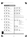
2. Data Transmission
■
Channel Voice Messages
●
Note off
Status
2nd byte 3rd byte
8nH kkH 40H
n = MIDI channel number: 0H - FH (ch.1 - 16)
kk = note number: 00H - 7FH (0 - 127)
* Note off message is sent out with the velocity of 40H.
●
Note on
Status 2nd byte 3rd byte
9nH kkH vvH
n = MIDI channel number: 0H - FH (ch.1 - 16)
kk = note number: 00H - 7FH (0 - 127)
vv = note on velocity: 01H - 7FH (1 - 127)
●
Control Change
* By selecting a controller number that corresponds to the setting of parameters of
controllers (Control Src, Foot Controller Assign), the RD-700 can transmit any control
change message.
* These messages are not transmitted when MIDI Tx Parameter is OFF.
❍
Bank Select (Controller number 0, 32)
Status
2nd byte 3rd byte
BnH 00H mmH
BnH 20H llH
n = MIDI channel number: 0H - FH (ch.1 - 16)
mm, ll = Bank number: 00 00H - 7F 7FH (bank.1 - bank.16384)
* When Rec Mode is ON (EDIT:Utility:Rec Setting:Rec Mode), these messages are
transmitted when Tone is selected.
* These messages are transmitted when Bank Select parameter is Set on MIDI Tx Part.
* The Bank Select Numbers corresponding to SRX series should be referred to the SRX
series owner’s manual.
❍
Modulation (Controller number 1)
Status 2nd byte 3rd byte
BnH 01H vvH
n = MIDI channel number: 0H - FH (ch.1 - 16)
vv = Modulation depth: 00H - 7FH (0 - 127)
* These messages are transmitted when Modulation lever is operated.
❍
Portamento Time (Controller number 5)
Status
2nd byte 3rd byte
BnH 05H vvH
n = MIDI channel number: 0H - FH (ch.1 - 16)
vv = Portamento Time: 00H - 7FH (0 - 127)
* These messages are transmitted when Portament Time is set in MIDI Tx Mode.
❍
Data Entry (Controller number 6, 38)
Status
2nd byte 3rd byte
BnH 06H mmH
BnH 26H llH
n = MIDI channel number: 0H - FH (ch.1 - 16)
mm, ll = the value of the parameter specified by RPN/NRPN
mm = MSB, ll = LSB
* These messages are transmitted when Bend Range value is set in MIDI Tx Mode.
❍
Volume (Controller number 7)
Status
2nd byte 3rd byte
BnH 07H vvH
n = MIDI channel number: 0H - FH (ch.1 - 16)
vv = Volume: 00H - 7FH (0 - 127)
* These messages are transmitted when PART VOLUME Slider is operated.
RD-700_e.book 151 ページ 2004年4月26日 月曜日 午前11時54分