


Sample Sequencer
General Description
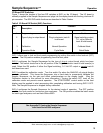
Output Boards and CRT Display
Output boards are available for the Sample Sequencer to provide a variety of outputs.
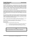
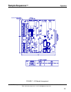
Valve Output Board
: The valve output board uses relays to turn on and off maximum 250 Volts (AC or
DC) electrically operated valves for switching up to eight sample streams to one analyzer. The board
may be located inside the Sample Sequencer. As an option, the valve output board may be housed in
a NEMA 4X enclosure for remote installations. The board includes lights to indicate current sample
point number. For use with the Sample Sequencer, Sentry offers a special sampling valve for stream
switching. The unique design prevents cross contamination and maintains continuously flowing
samples to help provide a representative sample.
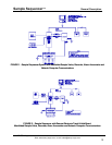
Signal Switching Output Board for Signal Switching or Contact Closure Point Indication
: The signal
switching output board with double pole, double throw relays is available to commutate the analyzer
analog signal (signal switching) and low voltage normally-open alarm outputs to eight individual outputs.
This output works well with a multipoint recorder with print holdout option. The signal switching output
board may also be used with a recorder which requires a contact closure to indicate the current sample
point number.
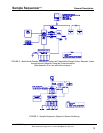
0-1 VDC Signal Output Board (optional)
: The 0 - 1 Volt DC signal output board is available to provide
an analog signal of 0 - 1 Volt DC indicating the current sample point number. For example, sample
point number one is indicated by an output of 0.1 Volt, point two by 0.2 Volt, ..., and point eight by 0.8
Volt. This option works well when there are insufficient channels on the recorder for all of the analog
signals. For example, it can be used when a two channel recorder is available to sequence more than
two streams. In addition, it can be used if each sample stream goes through multiple analyzers. The
board also provides eight commutated low voltage normally-open alarm contacts.
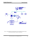
Electronic Track & Hold Boards:
Plug-in Type
: The plug-in electronic track & hold board installs inside the Sample
Sequencer and is used to track and hold a 0 - 20 or 4 - 20 milliamp signal as output for that point in up
to four separately isolated outputs. Two plug-in (6-02499E) electronic track & hold boards may be
plugged into the Sample Sequencer to obtain maximum eight points of track and hold output. The
electronic track & hold board has no alarms. Use the remote type electronic track & hold board (below)
with a signal switching output board if alarm contacts are required.
NOTE: Only one type
of signal output board, (i.e., signal switching, 0-1 VDC output, or two plug-in
electronic track & hold boards), may be used in
a Sample Sequencer at a time.
Remote Type
: The remote electronic track & hold board (7-00839A) is similar to the plug-
in type. However, it requires line power and contact closure inputs to indicate tracking sample point
number. This board is used in conjunction with the signal switching output board. See specification for
more information.
CRT Monitor Output
: A simple computer program can be written to communicate from the
controller computer to a remote computer, controller, or annunciator as all the information is available
and can be transmitted using RS-485. Additional Sample Sequencers may also be connected on the
RS-485 network. Sentry offers a computer program, SEQUENCE, to control, monitor, graph and
record data from a Sample Sequencer.
SENTRY Equipment Corp • P. O. Box 127 • Oconomowoc, WI 53066 • 262/567-7256 • FAX: 262/567-4523
Web: www.sentry-equip.com • e-mail: sales@sentry-equip.com
15