


Sample Sequencer
Table of Contents
List of Figures
Page
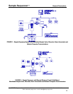
Figure 1: Sample Sequencer System with Manifolded Sample Valve,
Recorder, Alarm Annunciator and Network
Computer Communications ........................................................................12
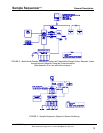
Figure 2: Sample Sequencer with Remote Electronic Track & Hold Board,
Manifolded Sample Valve, Recorder, Alarm Annunciator and
Network Computer Communications ..........................................................12
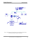
Figure 3: Batch Mode Sample Sequencer System with Manifolded Sample Valve,
Recorder, Alarm Annunciator and Network Computer Communications....13
Figure 4: Sample Sequencer System For Sensor Switching .....................................13
Figure 5: Sample Sequencer with Plug-In Electronic Track & Hold Board,
Manifolded Sample .....................................................................................14
Figure 6: Sample Sequencer Membrane Switch........................................................18
Figure 7: I/O Board Arrangement...............................................................................20
Figure 8: Cycle Mode Timing Diagram.......................................................................27
Figure 9: Batch Mode Timing Diagram (for Batch-Type Analyzers)...........................28
Figure 10: Sample Nametag ........................................................................................32
Figure 11: Panel Mounting & Overall Dimensions, Sample Sequencer.......................34
Figure 12: NEMA 4X Rear Cover & Surface Mounting, Sample Sequencer................35
Figure 13: Enclosure Overall Dimensions, Remote Track & Hold ..............................35
Figure 14: Remote Valve Board Enclosure..................................................................36
Figure 15: I/O Board Connections ...............................................................................37
Figure 16: Solenoid Sample Valve Connections..........................................................39
Figure 17: Sample Sequencer Assembly (Rear View).................................................40
Figure 18: Sample Sequencer Assembly with Plug-In Track & Hold ...........................41
Figure 19: Recorder Connections: Signal Switching Using Signal Switching
Output Board ..............................................................................................42
Figure 20: Recorder Connections: Contact Closure Channel Indication Using
Signal Switching Output Board ...................................................................43
Figure 21: Recorder Connections for One or More Analyzers Using 0-1 VDC
Output Relay Board ....................................................................................44
Figure 22: Recorder Connections Using Remote Track & Hold Output Board(s) &
Signal Switching Output Board ...................................................................46
Figure 23: Recorder Connections Using Plug-In Track & Hold Output Board(s) .........47
Figure 24: Alarm Connections .....................................................................................48
Figure B1: Recommended Sample Conditioning for Switching Streams to an
Analyzer......................................................................................................64
Figure C1: Remote Electronic Output Board Arrangement ..........................................65
Figure D1: Wiring to Hach Series 5000 Analyzer, Models 60000 - 60004 ...................69
Figure D2: Recommended Sample Conditioning for
Switching Streams to a Hach 5000 Analyzer ............................................70
Figure D3: Electrical Transmittal Sample Sequencer & Manifold valves......................71
Figure D4: Valve Transmittal Sample Sequencer & Manifold Valves...........................72
Figure E1: Sample Sequencer Basic Electrical Wiring Diagram ..................................73
Figure F1: Component View.........................................................................................74
Figure F2: Wiring Diagram - Dual Outputs from Plug-In Track Hold Board .................76
Figure H1: Remote T/H Board, Configuration for Voltage Input ...................................79
SENTRY Equipment Corp • P. O. Box 127 • Oconomowoc, WI 53066 • 262/567-7256 • FAX: 262/567-4523
Web: www.sentry-equip.com • e-mail: sales@sentry-equip.com
3