


Sample Sequencer
Specifications
GENERAL SPECIFICATIONS*
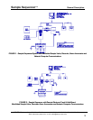
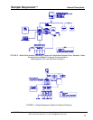
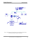
Applications: The Sample Sequencer is designed to support sample stream switching in the batch or
cycle modes. The Sample Sequencer can also switch sensor signals.
Design: Microprocessor-based with non-volatile memory and RS-485 communications
Maximum Number of Samples: 8
Power: 108-132/216-264 Vac, 47-63 Hz, Usage = 3.8VA without Plug-In Track & Hold (Uses external
UL/CSA or TUV-approved 6 VDC power supply.) Maximum 14VA with Plug-In Track & Hold.
Inputs from Analyzer:
• One analog input: 0-20 mA or 4-20 mA
• One digital input (dry contact closure) for indications of end-of-analysis signal for batch
mode operation
• One digital input (dry contact closure) for analyzer system alarm indication. This signal
shuts off Sample Sequencer and valves.
Outputs:
Standard Outputs:
• RS-485 serial communication port (for networking any RS-485 units to a PC)
• Valve Output Board to control maximum eight solenoid valves (DC or maximum 250 Vac
solenoids) for sample stream switching
• Plug-in Signal Switching Output Board with eight DPDT relays for analog signal switching
or contact closure for point number indication. The second pole of each point relay is used
for low voltage commutated analog alarm and analyzer system alarm indication for each
point.
Optional Input & Output Boards:
• Plug-in 0-1VDC Output Board with eight DPDT relays for 0-1 VDC output of sample point
number. The second pole of each point relay is used for low voltage commutated analog
alarm and analyzer system alarm indication for each point.
• Remote Electronic Track & Hold Board to output and hold analog signals (track & hold) of
four points. Two analog output boards may be used to provide eight total channels of
analog output. Use the remote electronic track & hold boards in combination with one
Plug-in Signal Switching Output Board.
• Remote Cell Switching Board to switch maximum eight cells
• Plug-In Track & Hold Board to output and hold four analog signals per circuit board. A
maximum of two plug-in Track & Hold boards may be installed in Sample Sequencer
enclosure. Use of two Plug-In Track & Hold boards requires that the valve circuit board be
mounted remote from Sample Sequencer.
Note: If you are retrofitting a Plug-In Track & Hold to an existing Sequencer in the field,
see Appendix G.
Accuracy of Sequencer: +/- 0.1% full scale, standard unit
+/- 0.2% full scale, with Internal Track & Hold Boards
User Interfaces: Integral membrane switch keypad and IBM compatible PC with serial port
* Sentry reserves the right to revise specifications at any time.
SENTRY Equipment Corp • P. O. Box 127 • Oconomowoc, WI 53066 • 262/567-7256 • FAX: 262/567-4523
Web: www.sentry-equip.com • e-mail: sales@sentry-equip.com
5