


Sample Sequencer
Operation
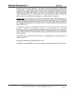
Advancing Streams
Sample streams may be advanced to any desired point number. Turn on the desired sample point
number by pressing the respective sample point number switch (1-8) and verifying the adjacent
point light is on. Then, turn off the intermediate point numbers and press the START/RESET key.
The desired sample point number will be on. Turn on previous sample points which are desirable.
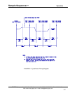
Holding on One Sample Point
Occasionally, it is necessary to hold an analysis on one sample point. Simply turn off all the
undesired sample points by using the respective sample point number switch (numbered 1-8 on
front display). The adjacent lights should turn off. Now, the Sample Sequencer will keep
sequencing on the one point. Thus, the normal cycle time, delay time and dwell times will be
used. Depending upon the programmed values for these times, one may or may not receive a
continuous analog signal through the Sample Sequencer.
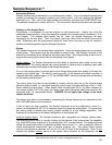
Alarms
The Sample Sequencer has several alarm capabilities. There are analog alarms and an analyzer
system alarm. These alarms may be annunciated in several ways. See Display Functions in this
manual for information about setting low and high alarm levels. See Programming to learn how to
program the analog alarm values from the Sequencer front display.
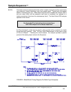
Analog Alarms:
The Sample Sequencer has the ability to determine and initiate low and high
analog alarms. The analog alarms may be annunciated in several ways, depending upon what
optional output boards are installed in the Sample Sequencer.
A low or high analog alarm is annunciated on the Sample Sequencer front display by blinking the
sample point number light. The blinking continues until: (1) the sample point alarm condition is
corrected and then sampled again, or (2) the ALARM RESET switch is pressed while not dwelling
on the alarming sample point.
The analog alarm may also be annunciated by contact closure using one of the optional signal
switching output boards, i.e., the Signal switching output board for signal switching or the 0-1 VDC
Signal switching output board. These boards have normally-open (N.O.) dry alarm contacts for
low voltage signals (<30 VDC) which are closed upon alarm during the dwell time period for the
respective point, i.e. commutated alarms. DANGER: Do not apply high voltage to the alarm
contact terminals!
The alarms may also be annunciated by connecting the Sample Sequencer to a computer via the
built-in RS-485 network communications.
In lieu of using dry alarm contacts, the Sample Sequencer may be configured to source (i.e.,
output), an unregulated 6 VDC 0.5 A maximum signal to indicate an analog alarm. The signal may
be used to power a remote relay having contacts suitable for a high voltage application. See
Appendix A for directions on the board configuration to accomplish this.
SENTRY Equipment Corp • P. O. Box 127 • Oconomowoc, WI 53066 • 262/567-7256 • FAX: 262/567-4523
Web: www.sentry-equip.com • e-mail: sales@sentry-equip.com
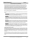
Analyzer System Alarm:
The Sample Sequencer also recognizes one analyzer system alarm.
The analyzer system alarm is normally initiated by the analyzer if the analyzer has this capability
(e.g. Hach 5000 series analyzers) by a normally-open (N.O.) contact closure. The analyzer should
initiate this system alarm when a significant problem has occurred, i.e., loss of reagents, failure of
critical measurement components, loss of sample pressure, etc. The system alarm contact
closure is recognized at terminals J4-2 and J4-5 on the I/O board of the Sequencer. Note: Do not
connect the analyzer analog
alarms to the system alarm terminals on the Sequencer as this
30