


Sample Sequencer
Installation
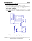
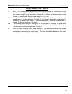
1. Connect the alarm terminals AL1 through AL8 on the signal switching board to the corresponding
annunciator N.O. terminals. Maximum recommended cable length is 32 ft. (or 10 m).
2. Connect the COM terminal on the signal switching board to a common terminal on the
annunciator. Jumper the annunciator common terminals together.
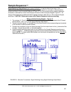
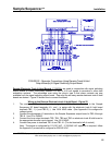
3. If the analyzer has a dry contact system
alarm, connect it to J4 terminals 2 and 5 on the I/O board
in the Sample Sequencer. Do not power these terminals. Note: Do not connect analyzer low
or high alarms to the Sequencer.
Starting Up The Sample Sequencer
Upon completing connection of the Sample Sequencer to the analyzer, valves, recorders, etc., as
described above, the following should be verified:
1. The plug-in boards (described above) should be snugly connected into the display board.
2. The rear cover should be installed on the Sequencer.
3. The Sample Sequencer is securely mounted.
4. The power may then be turned on. Consult the Operation section of this manual.
5. If there are problems, consult the troubleshooting section of this manual.
SENTRY Equipment Corp • P. O. Box 127 • Oconomowoc, WI 53066 • 262/567-7256 • FAX: 262/567-4523
Web: www.sentry-equip.com • e-mail: sales@sentry-equip.com
49