


Sample Sequencer
Installation
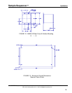
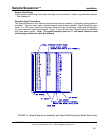
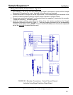
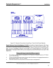
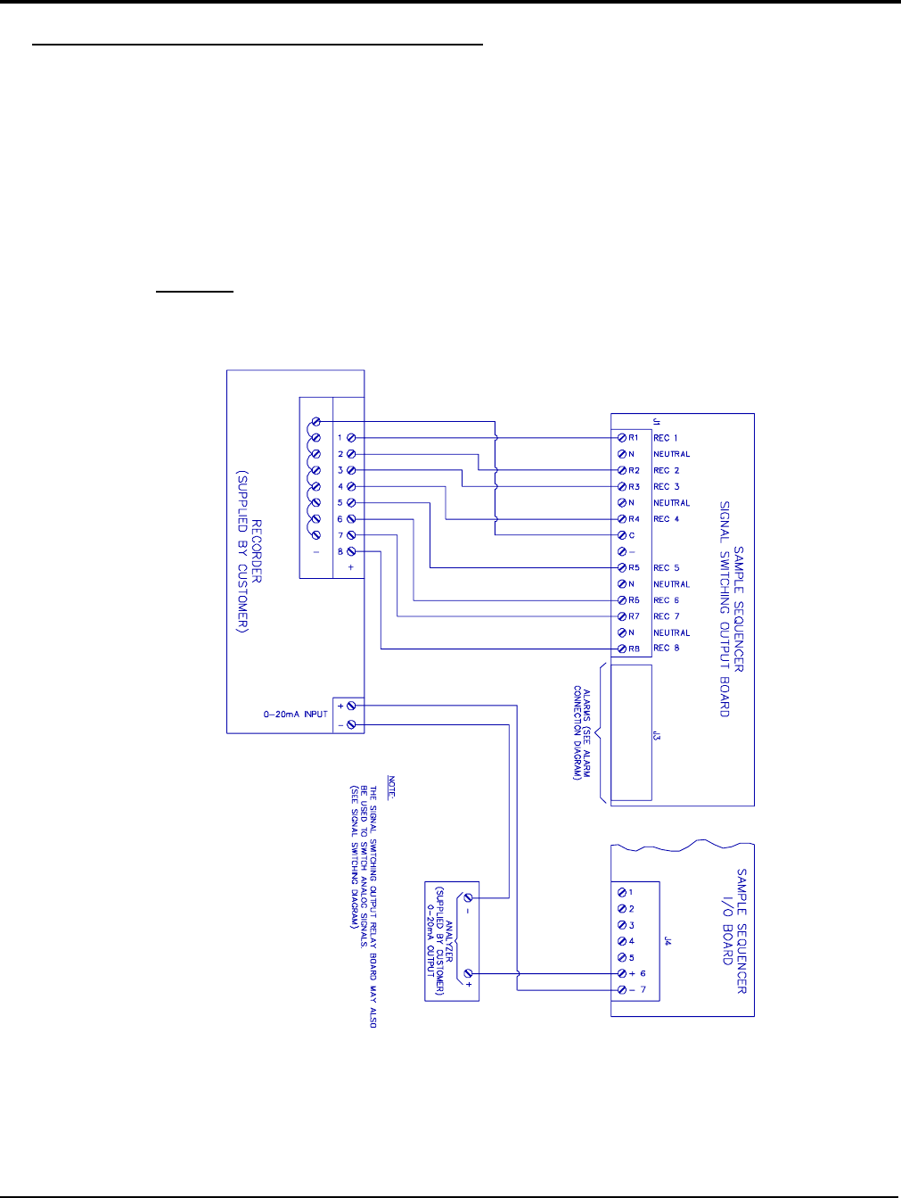
Wiring to Provide Dry Contact Closure - Figure 20
1. The analyzer 0 - 20 mA (or 4-20 mA) analog output signal is connected in series with the Sample
Sequencer I/O board and the + and - terminals on the recorder input terminals.
2. Connect terminals R1 through R8 on the output board, to the corresponding input terminals of the
recorder or data acquisition system for contact closure indication of sample number.
3. Connect one conductor to terminal C on the output board to a negative (-) terminal on the recorder.
Jumper the recorder (-) terminals together.
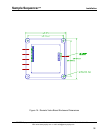
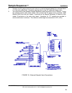
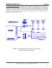
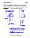
4. Install the signal switching output board in either of two slot locations marked on the Sample
Sequencer enclosure as shown in Figure 17. Install by plugging the board into the corresponding
connector of the display board. (NOTE: The board should be installed such that board components
are on the right side
as viewed from the rear.)
FIGURE 20 - Recorder Connections: Contact Closure Channel
Indication Using Signal Switching Output Board
SENTRY Equipment Corp • P. O. Box 127 • Oconomowoc, WI 53066 • 262/567-7256 • FAX: 262/567-4523
Web: www.sentry-equip.com • e-mail: sales@sentry-equip.com
43