


Sample Sequencer
Appendix G
Appendix G
Retrofitting a Plug-in (Internal) Track & Hold Board in the Field
Please, follow the below procedure if a plug-in (internal ) track & hold upgrade kit was purchased to
retrofit an existing Sample Sequencer in the field.
The upgrade kit should contain one or two (if ordered) plug-in track & hold boards, one 3 Amp fuse,
a new microprocessor and a 3 Amp 6 VDC power supply. If the kit with two boards was received,
an enclosure and cable for remote mounting of your existing valve relay board is also included. A
new microprocessor is also included.
Procedure
1. Disconnect power.
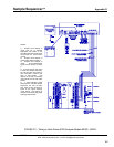
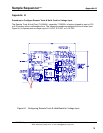
2. Disconnect wires and remove signal switching board. This board is the left-most board as
viewed from rear of the Sample Sequencer (See Figure 17). You may store this board
because it is not used in conjunction with the plug-in track & hold board feature.
3. If two
plug-in track & hold boards must be installed, disconnect wires and remove the valve
relay board (located in the center as viewed from rear). Install this board in the remote
enclosure provided with your track & hold retrofit kit. The valve board must be located
remote from Sequencer in order to install two plug-in track & hold boards.
4. At the I/O board (located on far right as viewed from rear), disconnect the power supply wires
from +6V and - terminals at J1 of I/O board.
5. Connect the new power supply (supplied in your retrofit kit) to the I/O board.
6. Replace the fuse (F1) on I/O board with the 3 Amp fuse included in your retrofit kit.
7. Inspect the date code on existing microprocessor (U3). If it is older than 8/95, replace it with
the new chip included with your upgrade kit.
8. Turn DIP switch SW1-2 on I/O board Off .
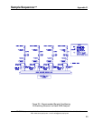
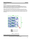
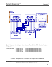
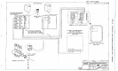
9. Install your new plug-in track & hold board in the far left slot for sample points 1-4. If you
purchased two plug-in track & hold boards, install the second board (Points 5-8) in the center
slot. Refer to Figure 18.
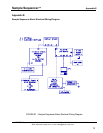
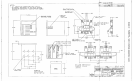
10. Connect output wiring to recorder or DCS from Plug-In Track & Hold Boards according to
Figure 23.
11. Apply power to the sample Sequencer by plugging in your new 6 VDC power supply.
12. The plug-in track & hold board will output and hold the respective 0-20 mA or 4-20 mA signal
after the respective point has gone through one Dwell time period.
SENTRY Equipment Corp • P. O. Box 127 • Oconomowoc, WI 53066 • 262/567-7256 • FAX: 262/567-4523
Web: www.sentry-equip.com • e-mail: sales@sentry-equip.com
76