


Sample Sequencer
Operation
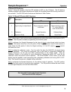
Display Functions:
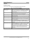
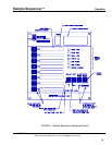
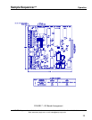
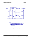
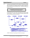
Functions shown in Figure 6 may be displayed on the Sample Sequencer. Pressing the DISPLAY key
toggles through the below functions. The light adjacent to the display function lights to indicate the function
is displayed. The NEXT key toggles through successive function point numbers (1-8) for ANALOG mA,
LOW ALARM and HIGH ALARM.
• CYCLE TIME (or time-out count-down for batch mode) - time duration to sample a point
• DELAY TIME - time to delay the analysis signal upon starting the cycle
• DWELL TIME - time period that analysis signal is read and switched after delay
• The following three items display milliamp values of 0 to 20 mA . Values for each of the
eight points are displayed by pressing the NEXT key.
ANALOG mA - the input analysis signal value
LOW ALARM values
HIGH ALARM values
• STATION NUMBER used in communications (1-16).
CYCLE TIME, DELAY TIME and DWELL TIME are discussed in the operating mode section below.
ANALOG mA Input Analysis Value
: All analog values are in milliampere form for either 0 to 20 or 4 to 20
milliampere range. On selection, the value for sample point number one is displayed. Pressing the NEXT
key will display the next higher point up to eight, and then from eight back to one. As the unit processes the
active sample points, any points not on will be skipped and the value zeroed. In cycle or batch mode
(described below) the values are retained only for the time required to complete an analysis circuit of the on
points. In manual mode only the active point is on. If the unit is in the OFF mode, all values are zeroed.
If an optional electronic track & hold board is used to provide individual milliampere outputs, all eight values
are refreshed each second. If a signal switching output board is used, the active value is output during the
dwell time only. All values are immediately available to a computer connected to the communication port.
LOW ALARM LEVEL:
The programmable low alarm level in milliamps is displayed for each sample point.
Pressing the NEXT key displays successive values. To reprogram a low alarm value, press the
PROGRAM key and follow the directions in the section on programming. Pressing the PROGRAM key
again terminates programming and saves the value in non-volatile memory. These values are also
programmed by communicating the required protocol from a connected computer and current values can
be sent, on request, from the Sample Sequencer to a computer. Note: The low and high alarm values are
programmed in milliamp values. Selection of the appropriate value should take the analyzer's
measurement range and span into consideration.
During the valid dwell output time, depending on the mode, the input signal is compared to the low alarm
level and if the signal is less, an alarm state is initiated for that point. The respective sample point light on
the Sample Sequencer display at that point selection switch will blink each second. Pressing the alarm
reset key stops the blinking, but the alarm can reinitiate if the condition still exists and is dwelling on the
point number. If an optional signal switching output board is used, a low voltage (<30 VDC) dry contact
closure alarm signal or 6 VDC output signal is commutated, depending on board configuration.
HIGH ALARM LEVEL:
Functions the same as for low alarms, but will go into alarm if the input signal is
equal to the programmed high alarm value.
SENTRY Equipment Corp • P. O. Box 127 • Oconomowoc, WI 53066 • 262/567-7256 • FAX: 262/567-4523
Web: www.sentry-equip.com • e-mail: sales@sentry-equip.com
STATION NUMBER:
The station number function assigns a station number of 1 to 16 to the Sample
Sequencer unit. The station number identifies the unit when operated with the built-in RS-485 serial
communication network. This station number should be different from other Sample Sequencers on the
computer network. The station number assignment can only be performed with the front panel display
23