


Sample Sequencer
Maintenance
SENTRY Equipment Corp • P. O. Box 127 • Oconomowoc, WI 53066 • 262/567-7256 • FAX: 262/567-4523
Web: www.sentry-equip.com • e-mail: sales@sentry-equip.com
51
16. Turn the DIP switch SW1-3 to off. This puts the Sequencer back into the normal operation
mode.
17. Turn power on. Analog input calibration is complete. Push START/RESET to restart the
Sample Sequencer.
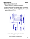
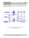
Analog Output Calibration of the Remote Electronic Track & Hold Board (7 -00839A)
Note: Sentry calibrates the Track and Hold card prior to shipping.
Tools Required:
A calibrated milliamp power source with digital display, calibrated milliamp meter and jumper wires are
required to calibrate the card. The recommended calibration procedure is:
1. Disconnect power to the Sample Sequencer and the Track and Hold card. Disconnect existing
wires to the Track and Hold board.
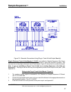
2. Jumper the four input channel terminals (CH1, CH2, CH3, CH4 on TB2) together to the ground
terminal (GND on TB2). See figure C1 in Appendix C.
3. Connect a calibrated milliamp source (0-20 mA) up to the (+) and (-) terminals on TB2.
4. Connect 110-120 VAC to TB1. (Use 220 VAC if configured such.)
5. Connect a calibrated milliamp meter to LOOP1 (TB6 (+) and (-) terminals).
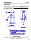
6. Input approximately 18-19 mA. Adjust the GAIN potentiometer (R43 for loop 1) until the output
signal measured by the meter matches the input signal.
7. Input approximately 4mA. Adjust the OFFSET potentiometer (R41 for loop 1) until the output
signal measured by the meter matches the input signal.
8. Repeat steps 5 through 6 until GAIN and OFFSET provide the correct signals.
9. Repeat steps 4 through 7 for LOOP2 (TB5), LOOP3 (TB4) and LOOP4 (TB3). The respective
GAIN and OFFSET potentiometers for these loops are adjacent to the corresponding LOOP
terminal block.
10. Calibration is now complete. Disconnect power and remove your meters and jumpers.
11. Reconnect wires to the Track and Hold card.
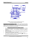
Analog Output Calibration of the Plug-in Electronic track & hold Board (Track & Hold)
Note: This calibration should occur after calibrating the analog input circuit on I/O circuit board.
1. Tools required: Calibrated milliampere power supply, multimeter with milliampere measurement
capability, Phillips and flat instrument screwdrivers.
2. Program the cycle time for one (1) second.
3. Turn off power to the Sample Sequencer.
4. Disconnect the existing analog input wires from the I/O board (at J4 on (+) and (-) terminals) and
connect a calibrated milliampere power supply.
5. On the rear of the I/O board, turn the DIP switch SW1-3 on. This switches the unit into the
calibrate mode.
6. Connect a milliamp meter to the (+) and (-) terminals of the desired output point on the electronic
track & hold board.
7. Turn power to the Sample Sequencer on. Push the NEXT button to display desired point.
8. Input 4 mA with the milliampere power source. Adjust the offset pot on track & hold circuit board
on the point being calibrated until the meter reading matches the sequencer analog mA display.
9. Input 20 mA with the milliampere power source. Adjust the gain pot on the track & hold board
point being calibrated until the meter reading matches the Sequencer Analog mA display.