


Sample Sequencer
Operation
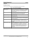
OPERATING MODES:
OFF, CYCLE, BATCH
OFF If there are no sample points on, or if a BATCH time out has occurred, or calibration has been used,
or after eight successive analyzer alarms, the Sample Sequencer goes into the OFF mode. This is
the normal preferred standby mode.
Even when the unit is "OFF", it is still able to:
Program
Calibrate
Communicate
A local or remote START/RESET starts the Sequencer again.
CYCLE This mode is for continuous output analyzers such as sodium, conductivity, pH, O
2
, some
colorimetric, and many others. Two system methods are used: sample stream switching
and sensor switching.
Sample Stream Switching
where successive sample streams are switched through the
same analyzer apparatus. An electrically actuated manifolded valve arrangement is
typically used to accomplish the stream switching. Sentry offers a technology-leading
sampling valve for stream switching.
Sensor Switching
where relatively simple sensors can be placed in each sample line and
the electrical leads to the analyzer can be successively switched to the analyzer.
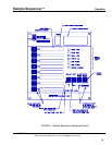
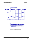
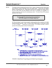
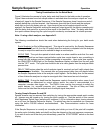
Timing Considerations for the Cycle Mode:
Figure 8 illustrates the concept of cycle, delay and dwell times for the cycle mode of
operation. Figure 8 demonstrates how each sample stream is switched for the duration
called cycle time. The analyzer output signal is switched through the Sample Sequencer
after the delay time period for the dwell time duration. When using the Sample Sequencer
for sensor switching, the only difference from stream switching is that the sensor signal is
switched instead of a valve during the cycle time. The following considerations should be
made when determining the timing for your system.
CYCLE Time
is the time period of each sample point during which stream or sensor signal
switching occurs. Shorter cycle times yield faster analytical updates among the points while
longer cycle times provide sufficient time to recognize stable readings. Short cycle times
are achievable by minimizing sample line length from the manifolded valve to the analyzer,
eliminating dead legs and by short analyzer response time. The cycle time may be
optimized by determining the maximum time period required for each sample point to
stabilize and using this as the cycle time. Note, the cycle time value must provide enough
time to fulfill the requirements for delay and dwell. For example, the cycle time must be long
enough for delay and dwell to count down before the next dwell time period initiates. (In
other words, the dwell time must be set less than or equal to the cycle time.)
SENTRY Equipment Corp • P. O. Box 127 • Oconomowoc, WI 53066 • 262/567-7256 • FAX: 262/567-4523
Web: www.sentry-equip.com • e-mail: sales@sentry-equip.com
DELAY Time
. After switching to a successive stream or sensor, there will be a settling time
for the analyzer to stabilize to the new sample: This DELAY time could be seconds to a
25