


Sample Sequencer
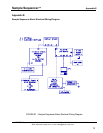
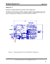
Appendix H
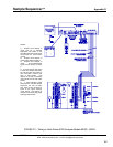
Notes:
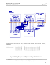
mA Configuration (Default Assembly)
R44=Zero ohm jumper installed.
J1=No component installed.
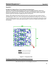
0-1 VDC Configuration
1. Remove Zero ohm jumper R44.
2. Install a 37 ohm resistor
1
at J1.
0-5 VDC Configuration
1. Remove Zero ohm jumper R44.
2. Install a 237 ohm resistor
1
at J1.
0-10 VDC Configuration (Use this config. with a Floating (isolated) or -10VDC Power Supply
2
)
1. Remove Zero ohm jumper R44.
2. Install a 487 ohm resistor
1
at J1.
3. Tie the "+" to "AGND" on TB2 with a jumper wire.
0-10 VDC Configuration (Use this configuration with a +10VDC Power Supply.
2
1. Install a 487 ohm resistor
1
to "+" on TB2. Connect the Vin positive wire to the resistor.
Sentry Equipment recommends soldering the positive wire to the resistor, and covering the
solder connection with heat shrink tubing.
1
1/4 Watt, 1% Metal Film Resistor
2
To determine the power supply type, use an Ohm Meter and measure the resistance
from the positive terminal to ground or negative terminal to ground. If the resistance is
<100 ohms between the positive terminal and ground, it's a - 10 vdc power supply. If the
resistance is <100 ohms between the negative terminal and ground, it's a +10 vdc
power supply. If the resistance is >100 ohms in either case, it's a floating 10 vdc input.
SENTRY Equipment Corp • P. O. Box 127 • Oconomowoc, WI 53066 • 262/567-7256 • FAX: 262/567-4523
Web: www.sentry-equip.com • e-mail: sales@sentry-equip.com
79