


Sample Sequencer
Appendix D
Appendix D
Instructions to Operate a Hach Series 5000 Analyzer with a Sample Sequencer
The Sample Sequencer may be operated with a Hach Series 5000 analyzer. The Series 5000
instruments operate in batch-mode style and require the appropriate configuration for use with the
Sample Sequencer. Hach 5000 analyzers have special features which provide a contact closure at
the end of the batch. This is called the Mark End of Measurement contact closure. The contact
closure causes the Sample Sequencer to advance the sample point number. See Batch Mode
operation description in this manual for more information.
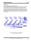
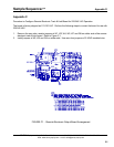
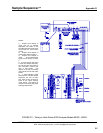
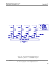
Figure D1 illustrates how to connect the Sample Sequencer I/O board to a Hach Series 5000
analyzer. The Hach 5000 analyzer must be configured properly to operate with the Sample
Sequencer. The analyzer should be configured to output a recorder signal of 4-20 mA. Further, the
analyzer must be programmed to use relay #3 and relay #4 for System Alarm and End-of-
Measurement contact closure indications, respectively. Consult the Hach analyzer manual for
information about configuring the Recorder output to 4-20 mA and the System Alarm to relay 3. The
following procedure describes how to configure the End-of-Measurement contact closure on the Hach
5000.
Configuring the Series 5000 (Catalog No. 60000-XX through 60004-XX) for MARK END OF MEASURE on
Relay 4
1. Remove the front cover of the control module. Move the No. 1 DIP switch on SW1 to the ON position.
This will enable the Extended Diagnostic menu. (Switch SW1 is an 8-switch DIP located near center
of circuit board.)
2. Return to the front of the control panel and press the TEST key. Using the NEXT key, scroll through
the diagnostic menu to MARK END OF MEAS. Then, press ENTER and select ENABLE with the
NEXT key. Then, press ENTER. This will activate the MARK END OF MEASURE contact closure.
3. Turn OFF switch No. 1 on switch bank SW1 of the circuit board. This will return the analyzer to
normal operation but leave the MARK END OF MEASURE function enabled. Note: This procedure
will have to be repeated if a cold start is performed.
4. Reassign alarm 2 to relay 2 by the following: Press SET UP key. ALARMS will appear. Press
ENTER. Then, scroll with the NEXT key to RELAY CONFIG and press ENTER. Scroll to ALARM 2
with the NEXT key and then press ENTER. Scroll with the NEXT key to RLY 2 and press ENTER.
5. Assign relay 4 to mark end of measure by the following: Press SETUP key on the control module.
ALARMS will appear. Press ENTER. Then, scroll with the NEXT key to RELAY CONFIG and press
ENTER. Scroll to MARK END OF MEAS and press ENTER. Note: MARK END OF MEAS will not
appear unless it has been properly activated per the above steps. Scroll with the NEXT key to
ALARM 4 and press ENTER. This will assign the alarm 4 relay to mark the end of measurement with
a contact closure. The contact closure makes the Sample Sequencer advance to the next sample
point.
6. Verify the switches (SW1) on Sample Sequencer I/O board are positioned per Figure D1.
SENTRY Equipment Corp • P. O. Box 127 • Oconomowoc, WI 53066 • 262/567-7256 • FAX: 262/567-4523
Web: www.sentry-equip.com • e-mail: sales@sentry-equip.com
65