


Sample Sequencer
Installation
I/O Board Connections and Settings
CAUTION: Disconnect power to the Sample Sequencer before proceeding with installation.
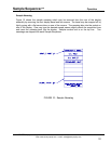
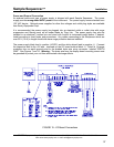
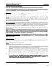
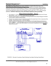
Figure 13 shows connections made to the I/O board. All wiring to the I/O board should be performed
with 22 gauge conductor. However, the ground should be 14 gauge minimum.
Analog Input
: Connect the analog signal from the analyzer to the + and - terminals on J4 using 22
gauge conductor. Maximum recommended length is 32 ft (10m).
RS-485
: Connect J6-6 modular plug with flat or round cable into terminals J2 and/or J3. These
terminals may be daisy-chained to other devices on the same RS-485 network. See the I/O board
arrangement diagram for proper polarity of conductors. Only the two center conductors are used for
RS-485 communication. Long distances, i.e., greater than 100 feet, should use twisted pair cable to
eliminate RFI and EMI noise interference on the network.
Analyzer system alarm
: Connect the analyzer system alarm (not analog alarm) to terminals 2 and 5 on
J4. This should be a non-powered line used for dry-contact closure indication only. Use 22 gauge
conductor cable up to 32 ft. (10m) length. NOTE: Do not connect, analyzer analog alarms to these
terminals! See Alarms. If using a Hach 5000 analyzer, see Appendix D for wiring diagram.
End-of-Analysis
: For batch mode operation (see Operating Modes in this manual), connect the
appropriate terminals from a batch type analyzer to terminals 3 and 4 on J4 using 22 gauge conductor
cable up to 32 ft. (10m) length. Consult the analyzer manual to properly configure the analyzer to send
an end-of-analysis signal. Note: These terminals are not used when operating the Sample Sequencer
in the cycle mode. If using a Hach 5000 analyzer, see Appendix D.
Connections to Valve Output Board
: Using the supplied 22 gauge eight conductor (Belden 8456) cable,
connect the appropriate color lead to the labeled terminals on J1. Maximum recommended cable
length is 32 ft. (10m).
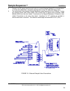
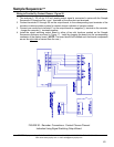
DIP Switch Settings:
See Table 2 and Figure 7 for proper settings of the DIP switch bank (SW1) on the
I/O board. These switches must be set correctly for the Sample Sequencer to operate as required.
Power:
See Power and Ground Connections
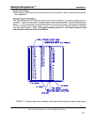
Sample Valve Electrical Connection to Valve output board
1. Determine the power source for the electrical valves. Sentry Equipment offers a special sample
valve manifold with optional DC power supplies for DC solenoids if required
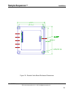
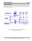
2. DANGER: To avoid danger, disconnect power before performing this step. Connect the valve
power source conductors (choose the appropriate gauge size for the breaker amp service at job
site) to terminals labeled + and - on J1 of the Valve output board. This board is installed inside
the Sample Sequencer or, as an option, in a remote NEMA 4X enclosure. Knockouts for 1/2"
conduit are provided. Seal any unused knockouts. See Figure 16 for the wiring drawing.
3. Connect one 22 gauge wire from each valve to terminals V1 through V8 on terminal block J1 of
the valve output board. WARNING: If the Sentry sample valve with integral 3/8" cable grip
connector is used, the valve cable selected must fit snugly in the 3/8" connector. A
larger gauge size may be necessary to achieve snug fit.
SENTRY Equipment Corp • P. O. Box 127 • Oconomowoc, WI 53066 • 262/567-7256 • FAX: 262/567-4523
Web: www.sentry-equip.com • e-mail: sales@sentry-equip.com
38