


Sample Sequencer
Maintenance
MAINTENANCE
Fuses
There are fuses on the Sample Sequencer to protect personnel, wiring and the electronics from
excessive current draw. Every board except the display board contains one fuse.
The I/O board fuse is a 3 Amp subminiature 2AG fast blow (Littelfuse 225.003).
The valve and signal switching boards fuse use a 1 amp subminiature 2AG fast blow. (Littelfuse
225.001). The parts may also be purchased from Sentry. See the Spare parts list. Note: Disregard
500 mA marking on I/O board.
If a board does not function, check the fuse for continuity to determine if it is defective. Note, the small
fuse wire may appear intact; however, it commonly breaks at a spot not visible.
Calibration
Note: The analog circuitry of the Sample Sequencer is calibrated at Sentry prior to shipment.
Re-calibration should be performed by properly trained personnel. Refer to the following procedures
to calibrate the analog circuits of the Sample Sequencer:
Analog Input Calibration
1. Tools Required: Calibrated milliampere supply and Phillips and flat instrument screwdrivers.
2. Turn off power to the Sample Sequencer.
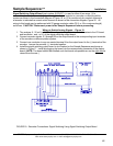
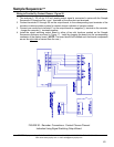
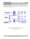
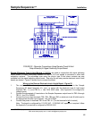
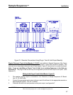
3. Remove the existing analog input wires. See Figure 7 for board and terminal locations.
4. Snap off the front bezel on the Sample Sequencer by hand or lightly with a small flat
screwdriver.
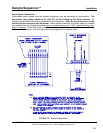
5. Remove the four corner mounting screws. Use a small flat screwdriver to carefully pry out the
display board assembly and connected boards approximately one inch. The calibration
potentiometers are visible on the left edge (from front of Sequencer) of the display board.
6. Verify the boards are still plugged into the display board.
7. On the rear of the I/O board, turn the DIP switch SW1-3 on. This switches the unit into the
calibrate mode.
8. Turn on power to the Sample Sequencer.
9. Disconnect the input to the Sequencer and examine the ANALOG mA display on front of the
Sample Sequencer to verify 0 mA. Using a small flat instrument screwdriver, adjust the offset
potentiometer (R5) until the display reads 0 mA. (The offset pot is the top pot visible on the left
edge of display board.)
10. Input 20 to mA to the Sample Sequencer and examine the ANALOG mA display on front of the
Sequencer. Adjust the gain potentiometer (R6) until the display reads the same input 20 mA.
(The gain pot is the bottom pot on the left edge of the display board.)
11. Repeat steps 9 and 10 until an accurate calibration is obtained.
12. If the signal switching output board is installed, one may check the recorder calibration on each
individual point by repeatedly pressing the "NEXT" key on the Sequencer while in the calibrate
mode. This will verify recorder operation with the milliampere calibration signal on each point.
13. Turn off power to the Sample Sequencer.
14. Slide the display board and interconnected boards back into the enclosure. Replace the four
screws and bezel.
15. Remove the calibrated power supply and reconnect the analog input signal wires.
SENTRY Equipment Corp • P. O. Box 127 • Oconomowoc, WI 53066 • 262/567-7256 • FAX: 262/567-4523
Web: www.sentry-equip.com • e-mail: sales@sentry-equip.com
50