


Sample Sequencer
Installation
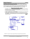
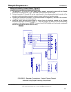
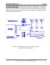
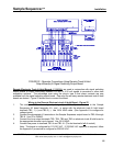
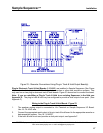
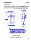
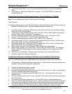
Figure 23 - Recorder Connections Using Plug-in Track & Hold Output Board(s)
Plug-In Electronic Track & Hold Boards (6-02499E)
are installed in Sample Sequencer (See Figure
18) to output individually isolated 0-20 mA signals to recorders or other data acquisition systems. One
may use one or two plug-in electronic track & hold boards. Figure 23 shows how to connect the board.
Note: If you are retrofitting a Plug-In Track & Hold to an existing Sequencer in the field, see
Appendix G. The plug-in track & hold may be configured to provide a dual output of one point. (See
Appendix F)
Wiring to the Plug-In Track & Hold Board - Figure 23
1. The analyzer analog output is connected to J4+/-Terminal on Sample Sequencer I/O Board.
Use 18 - 24 AWG wire.
2. Connect the appropriate point output of plug-in track & hold board to the appropriate recorder or
data acquisition system. Use 18 - 24 AWG.
3. If the track & hold circuit card provides a dual point output, see Appendix F.
SENTRY Equipment Corp • P. O. Box 127 • Oconomowoc, WI 53066 • 262/567-7256 • FAX: 262/567-4523
Web: www.sentry-equip.com • e-mail: sales@sentry-equip.com
47