


Sample Sequencer
Appendix A
Appendix A
Configuring the Sample Sequencer to Output 6 Volt DC on Alarm Contacts of Signal Switching
Output Board
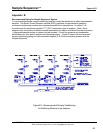
The Sample Sequencer may be configured to output, (i.e., source), unregulated 6 VDC on the alarm
contacts of the signal switching or 0-1VDC output boards if desired. This can be used for applications
where remote relays or other devices must be powered for alarm annunciation. This modification may
be necessary because the signal switching output board alarm contacts should not be powered above
30 VDC and 1A.
The unregulated 6 VDC can power a remote relay coil used to switch a high voltage signal.
Procedure to Configure the Sample Sequencer to Output 6 VDC on Alarm Contacts
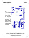
1. Disconnect power from the Sample Sequencer and remove the I/O board.
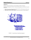
2. Cut jumper W1 off from the I/O board. (Refer to Figure 7 for location of W1.)
3. Install a jumper in W2 and W3.
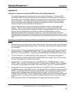
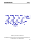
4. Insert the I/O board back into correct slot (see Figure 17) of Sample Sequencer.
5. The unit is now ready to operate. Note, a signal switching output board or 0-1 VDC
output board must be used to obtain the 6 VDC alarm signal.
SENTRY Equipment Corp • P. O. Box 127 • Oconomowoc, WI 53066 • 262/567-7256 • FAX: 262/567-4523
Web: www.sentry-equip.com • e-mail: sales@sentry-equip.com
62