


Sample Sequencer
Appendix F
Appendix F
Procedure to Configure Plug-In Track & Hold for Dual Point Output
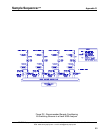
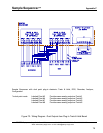
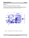
The Plug-In Track & Hold circuit card plugs into slots 2 and 9 of Sample Sequencer enclosure as
optional cards. When the Track & Hold Board is in number 2 slot (left board in Figure 18), it normally
provides an analog output from 1 thru 4 points. When the track & hold card is used in number 9 slot
(center in Figure 18), it provides an analog output from 5 thru 8 points.
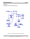
However, after configuring the track & hold circuit card for dual output mode, slot number 2 Track &
Hold Board points 1 and 3, and, 2 and 4 will output the same sample point analog value. Slot number 9
Track & Hold Board points 5 and 7, and, 6 and 8 will output the same sample point analog values. Dual
outputs may be required in cases when separate signals to a recorder and digital control system (DCS)
are necessary.
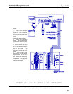
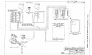
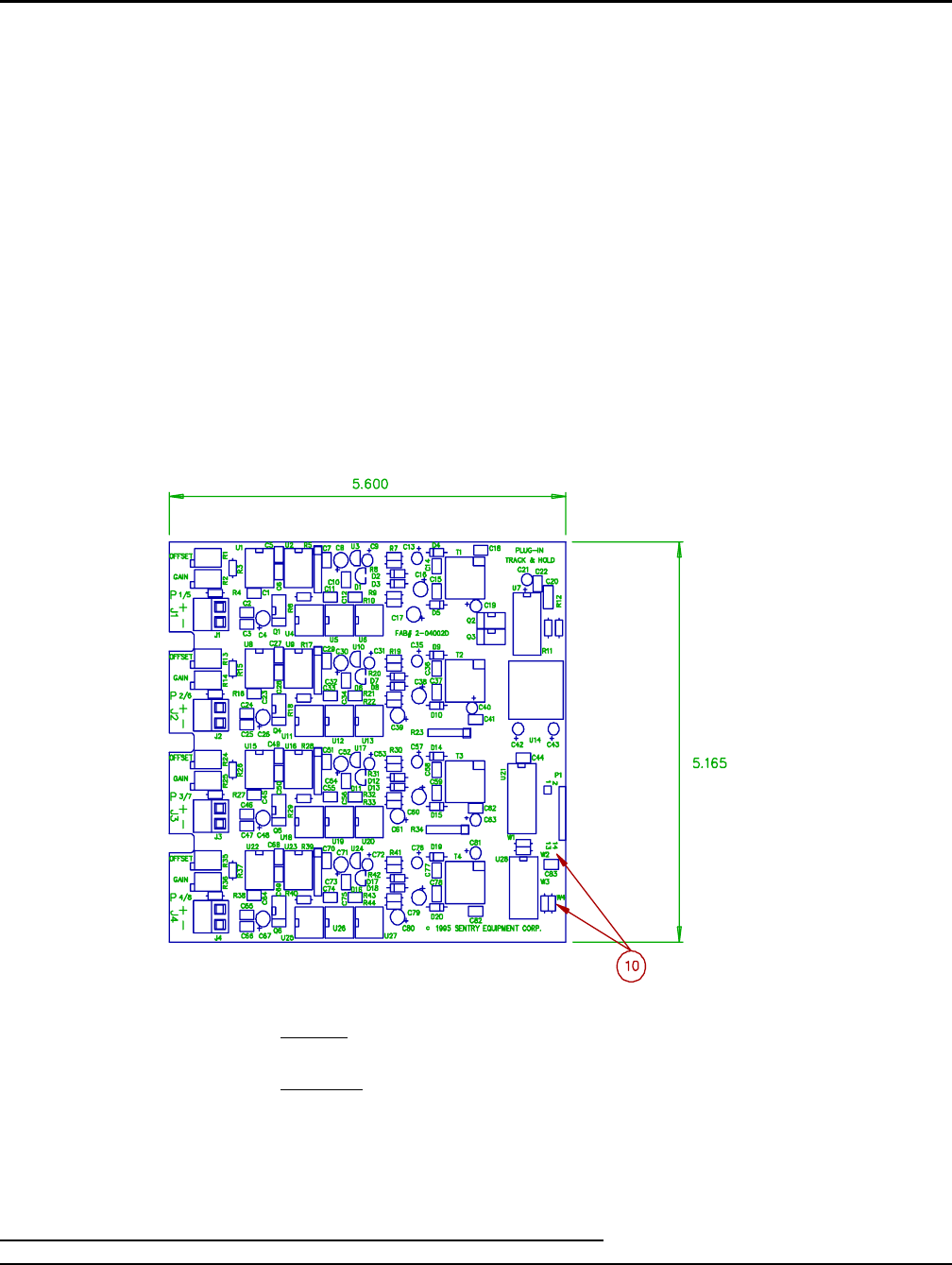
Normal Mode
J3 is Normal point 3/7 mode (W1 removed, W2 installed)
J4 is normal point 4/8 mode (W3 removed, W4 installed)
Dual Point Mode
J3 is dual point 1/5 ,mode (W1 installed, W2 Removed)
J4 is dual point 2/6 mode (W3 installed, W4 removed)
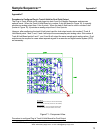
Figure F1 - Component View
SENTRY Equipment Corp • P. O. Box 127•Oconomowoc, WI 53066 • 262/567-7256 • FAX: 262/567-4523
Web: www.sentry-equip.com • e-mail: sales@sentry-equip.com
Procedure to configure Plug-In Track & Hold Boards for Dual Output
73