


16
VR800 Owner’s Manual (Names and Functions)
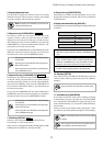
REMAIN
SETUP
COMPLETED !
SURE ?
MTC OFFSET
PGM
TEMPO
VARI PITCH
44.1kHz
MTC IN
LOC
ABS
MTC
Lights up when ABS is selected as time base.
Lights up when MTC is selected as time base.
Lights up to indicate available recording time and
space on the disk.
Lights up when the VR800 enters SETUP mode.
Lights up when an edit operation (copy, move,
paste, or erase) is completed.
Lights up to confirm or cancel the operation when
you are making settings or edits.
Lights up when the MTC Offset menu is selected in
SETUP mode.
Lights up to indicate the current program number.
Lights up when the tempo setting menu is selected
in SETUP mode.
Lights up when vari pitch mode is turned on.
The VR800 displays the sampling frequency.
If the sampling frequency of the program is different
from the setting for the incoming signal, the indicator
flashes. If the sampling frequency of the incoming
S/P DIF digital signal is different from the setting,
both [DIGITAL] and [44.1kHz] flash.
Lights up to indicate that MTC is input from an
external MIDI device to the VR800.
Lights up when the VR800 enters locate point (edit
point) edit mode.
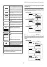
The level meter shows the recorder output level and the
recording level for tracks 1~8.
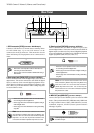
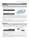
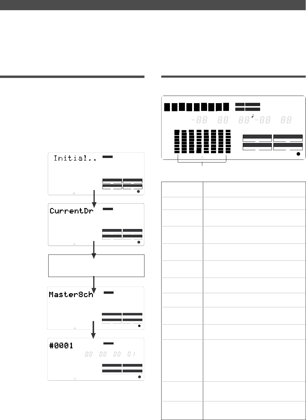
Preset display
The display below shows all preset items for explanation
purposes.
Display Section
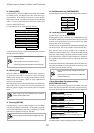
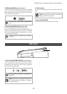
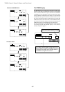
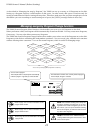
Indicating time base
ABS 0 (top of the disk)
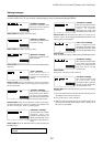
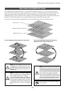
When the VR800
recognizes the current
drive, the [SCSI]
indicator lights up in the
[DRIVE] section of the
display if the current
drive is a SCSI device.
The [IDE] indicator
lights up if the current
drive is an E-IDE hard
disk.
The name of the SCSI drive (The name is
different, depending on the type of device.)
Indicating a recording
mode used during for-
matting.
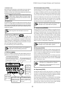
Display when the power is turned on
When you turn on the power to the VR800 and the
connected external SCSI drive (a formatted removable disk
or hard disk), the display shows the [Initial...] message,
[Current Dr], the name of the connected current drive, then
recording mode (Master 8ch, Master 4ch, or ADAC 8ch),
and finally the top position of the disk in the time base
(ABS, MTC, or BAR/BEAT/CLK) used in the last program
before you turned the power off.
The following example indicates that the VR800 started with
the ABS time base used in program 1.
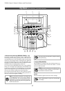
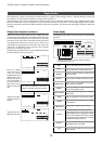
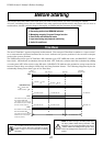
The VR800 uses a liquid crystal display which integrates a 9-digit/35-dot message section, 7-segment display section, and
level meters. The level meters indicate the output level of tracks 1-8.
The time display shows various information in different units, such as ABS time (absolute time), MTC (MIDI timecode), BAR/
BEAT/CLK (bar/beat/clock), and makes it easy to check the recorder’s current time. The message display shows various
messages required to operate the VR800, and offers interactive operation. This section describes display functions along with
examples.
CLK
SYNC OUT DRIVE
SCSI
AUTO A.PUNCH
SMF
PGM
ABS
44.1kHz
DIGITAL
SYNC OUT DRIVE
SCSI
AUTO A.PUNCH
DIGITAL
44.1kHz
DRIVE
AUTO A.PUNCH
SYNC OUT
SCSI
44.1kHz
DIGITAL
SYNC OUT DRIVE
SCSI
AUTO A.PUNCH
44.1kHz
DIGITAL
CLK MTC
SYNC OUT DRIVE
IDE SCSI
PLAY RTN
AUTO A.PUNCH
RHSL TAKE
REMAIN
LOC
VARI PITCH
SETUP
BAR
SMH
CLK
F
MB
SF
SURE ? COMPLETED!
MIDI
MTC
SLAVE
DIGITAL
TEMPO
PGM
MTC
OFFSET
ABS
MTC IN
44.1kHz
%