


172
Chapter 9 Parameter Guide SYSTEM
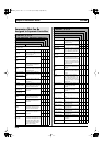
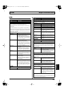
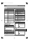
OUTPUT
* The parameters enabled (MAIN OUT, MAIN LEVEL, SUB OUT,
SUB LEVEL, D OUT, D OUT LEVEL) change according to the
OUTPUT MODE settings.
When they are disabled, the value < > is given.
Parameter/
Range
Explanation
OUTPUT MODE
SYSTEM
The values set in the SYSTEM parameters
MAIN OUT, MAIN LEVEL, SUB OUT, SUB
LEVEL, D OUT, and D OUT LEVEL are en-
abled.
PATCH The values set in MAIN OUT, MAIN LEV-
EL, SUB OUT, SUB LEVEL, D OUT, D OUT
LEVEL for each patch are enabled.
MAIN OUT
This switches the signals output to MAIN OUT.
CH A This outputs Channel A.
The mixer’s MIX SW, PAN, LEVEL, and A/
B BAL are also reflected here.
CH B This outputs Channel B.
The mixer’s MIX SW, PAN, LEVEL, and A/
B BAL are also reflected here.
MIXER (DRY) This outputs the post-A/B mix signals be-
fore application of DELAY/REVERB.
MIXER This outputs the post-A/B mix signals after
application of DELAY/REVERB and TO-
TAL EQ.
MAIN LEVEL
0–200
Adjusts the level to MAIN LEVEL.
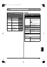
SUB OUT
This switches the signals output to SUB OUT.
CH A This outputs Channel A.
The mixer’s MIX SW, PAN, LEVEL, and A/
B BAL are also reflected here.
CH B This outputs Channel B.
The mixer’s MIX SW, PAN, LEVEL, and A/
B BAL are also reflected here.
MIXER (DRY) This outputs the post-A/B mix signals be-
fore application of DELAY/REVERB.
MIXER This outputs the post-A/B mix signals after
application of DELAY/REVERB and TO-
TAL EQ.
SUB LEVEL
0–200 Adjusts the level to SUB OUT LEVEL.
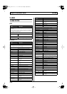
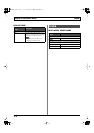
Parameter/
Range
Explanation
D OUT (Digital Out)
This switches the signals output from DIGITAL OUT.
COSM GTR A This outputs the sounds from COSM GTR
A.
COSM GTR B This outputs the sounds from COSM GTR B.
NORMAL PU This outputs the sounds from the normal
pickup.
CH A This outputs Channel A.
This output also reflects the mixer’s MIX
SW, PAN, LEVEL, and A/B BAL settings.
CH B This outputs Channel B.
This output also reflects the mixer’s MIX
SW, PAN, LEVEL, and A/B BAL settings.
MIXER (DRY) This outputs the post-A/B mix signals be-
fore application of DELAY/REVERB.
MIXER This outputs the post-A/B mix signals after
application of DELAY/REVERB and TO-
TAL EQ.
MAIN OUT This outputs the same signals as those from
MAIN OUT.
SUB OUT This outputs the same signals as those from
SUB OUT.
D OUT LEVEL (Digital Out Level)
0–200
Adjusts the level to DIGITAL OUT.
VG-99_e.book 172 ページ 2007年7月5日 木曜日 午前9時22分