


73
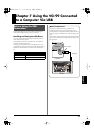
Chapter 7 Using the VG-99 Connected to a Computer Via USB
Chapter 7
The following section describes the VG-99’s USB-related functions.
Make these settings in accordance with how you plan to use the VG-
99.
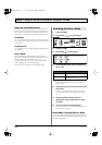
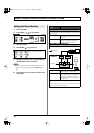
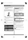
1.
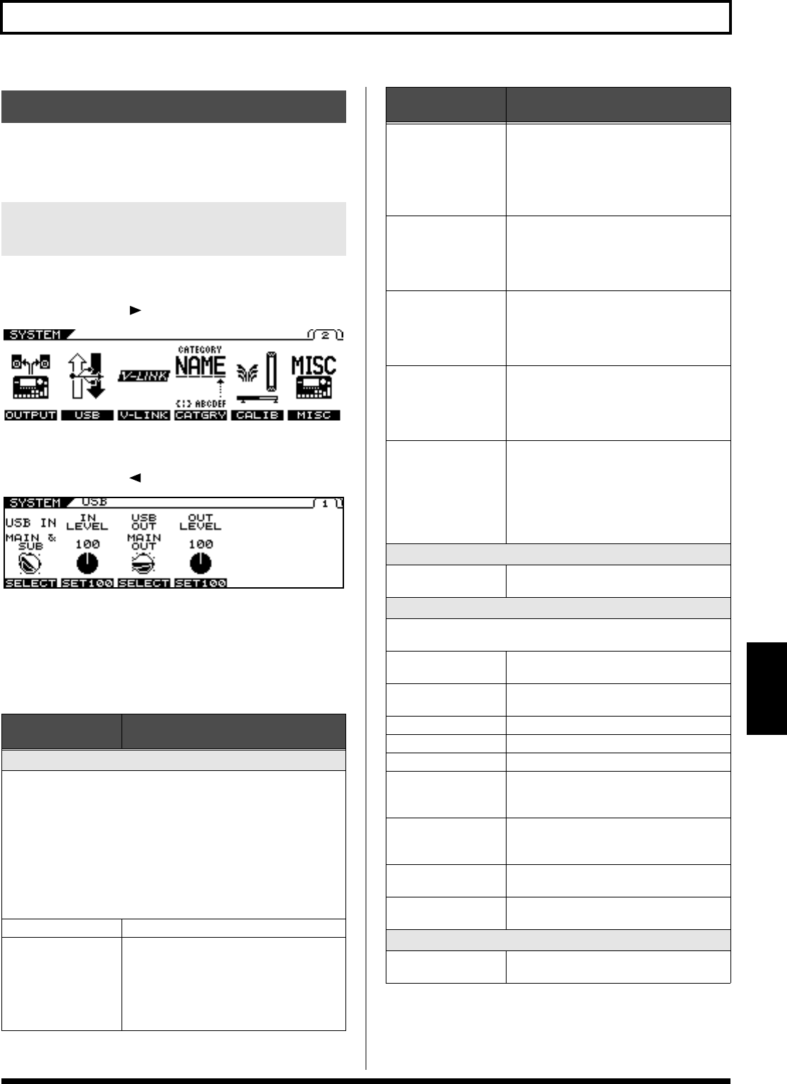
Press [SYSTEM].
2.
Press PAGE [ ] to go to Page 2.
3.
Press [F2] (USB).
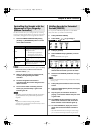
4.
Press PAGE [ ] to go to Page 1.
5.
Change the setting’s value with [F1]–[F4] or
the F1–F4 knobs.
6.
Press [EXIT] one or more times to return to the
Play screen.
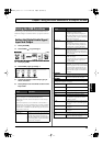
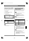
Setting the USB Functions
Setting the Digital Audio Signal
Input and Output
Parameter/
Range
Explanation
USB IN
This sets the point at which digital audio signals received via USB
(from your computer) are connected within the VG-99.
* Unless this is set to OFF, make sure the software is not set to thru for
audio signals.
* If the USB IN parameter is set to COSM GTR A, COSM GTR B, or
NORMAL PU, the setting automatically changes to MAIN & SUB the
next time the VG-99 is powered up. If you plan to use COSM GTR A,
COSM GTR B, or NORMAL PU, make the setting each time you turn
on the power to the VG-99.
OFF
The signals are not connected at any point.
COSM GTR A The signals are connected at the point where
the COSM GUITAR A is output.
The audio output from the computer, in-
stead of the COSM guitar sounds played by
the connected guitar, is input to the effects.
* POLY FX are not applied.
COSM GTR B
The signals are connected at the point where
the COSM GUITAR B is output.
The audio output from the computer, in-
stead of the COSM guitar sounds played by
the connected guitar, is input to the effects.
* POLY FX are not applied.
NORMAL PU
The signals are connected at the normal
pickup input.
The audio output from the computer, in-
stead of the normal sounds played by the
connected guitar, is input to the effects.
MAIN OUT The signals are connected at the point where
MAIN OUT is output.
The signals from the VG-99’s MAIN OUT
and the audio output from the computer are
mixed and output.
SUB OUT The signals are connected at the point where
SUB OUT is output.
The signals from the VG-99’s SUB OUT and
the audio output from the computer are
mixed and output.
MAIN&SUB The signals are connected at the point where
both MAIN OUT and SUB OUT are output.
Each of the signals from the VG-99’s MAIN
OUT and the audio output from the com-
puter are mixed, SUB OUT and the audio
output from the computer are mixed from
the output.
IN LEVEL
0–200
Adjusts the volume level of the digital audio
received via USB (from the computer).
USB OUT
This sets the point internally within the VG-99 from which signals
are output via USB (to the computer).
COSM GTR A The output from COSM GUITAR A is out-
put.
COSM GTR B The output from COSM GUITAR B is out-
put.
NORMAL PU The normal pickup input is output.
CH A The output from Channel A is output.
CH B The output from Channel B is output.
MIXER (DRY) The signals that have been mixed with the
mixer, but before application of DELAY/
REVERB, are output.
MIXER The signals that have been mixed with the
mixer and have DELAY/REVERB applied
are output.
MAIN OUT The same signals as those from MAIN OUT
are output.
SUB OUT The same signals as those from SUB OUT
are output.
OUT LEVEL
0–200
Adjusts the volume level of the digital audio
output via USB (to the computer).
Parameter/
Range
Explanation
VG-99_e.book 73 ページ 2007年7月5日 木曜日 午前9時22分