


18
Chapter 1 Outputting Sounds
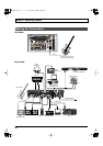
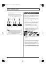
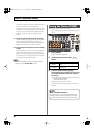
* You can connect two FS-5Us using the special Roland PCS-31
connection cable (optional).
* When an FS-6 is connected to the CTL3,4 jack with an optional
connection cable (stereo 1/4” phone
–
stereo 1/4” phone), pedal
switch B operates according to the CONTROL 3 settings, and pedal
switch A operates according to the CONTROL 4 settings.
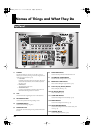
fig.01-030
941
Once the connections have been completed p. 16, turn on power to
your various devices in the order specified. By turning on devices in
the wrong order, you risk causing malfunction and/or damage to
speakers and other devices.
942
• This unit is equipped with a protection circuit. A brief
interval (a few seconds) after power up is required before
the unit will operate normally.
943
• Always make sure to have the volume level turned down
before switching on power. Even with the volume all the
way down, you may still hear some sound when the
power is switched on, but this is normal, and does not
indicate a malfunction.
* Turning on devices in the wrong sequence may result in
malfunction and/or damage to speakers and other devices.
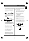
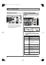
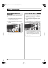
1.
Switch on the POWER switch on the VG-99’s
top panel.
The display changes as described below, and after several
seconds the VG-99 is ready for normal performance.
This screen is called the “Play screen.”
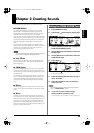
fig.01-060d
Unless special note is made otherwise, the operations
described in this manual are carried out with the Play screen
displayed.
* When the power to the VG-99 is turned on, the patch selected at the
time the power was last turned off is called up.
985
• The explanations in this manual include illustrations that
depict what should typically be shown by the display.
Note, however, that your unit may incorporate a newer,
enhanced version of the system (e.g., includes newer
sounds), so what you actually see in the display may not
always match what appears in the manual.
2.
Turn on the power to the guitar amp or mixer.
* Raise amp volume levels only after turning on the power to all the
devices.
PCS-31 cable
To CTL3,4 jack To CTL3,4 jack To CTL3,4 jack
White Red White Red
BOSS
FS-5U
(CTL3)
BOSS
FS-5U
(CTL4)
(CTL3) (CTL4)
(CTL4) (CTL3)
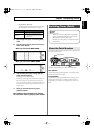
• When using the VG-99 with an expression pedal connected
to the EXP PEDAL jack, make the settings described on p.
154.
• When using the VG-99 with a footswitch connected to the
CTL3/4 jack, make the settings described on p. 154.
Turning On the Power
VG-99_e.book 18 ページ 2007年7月5日 木曜日 午前9時22分