


175
SYSTEM Chapter 9 Parameter Guide
Chapter 9
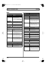
*1 You cannot set the MIN or MAX parameters when the TARGET
parameter is set to one of the functions below. The MIN
parameter is fixed at 0, and the MAX parameter is fixed at 127.
• SCRTCH SW
• BPM SYNC
• CLIP LOOP
• AB SW
• TAP SW
• DUAL STREAM
*2 The TRIGGR, TIME, and CURVE parameters are enabled when
the SOURCE parameter is set to INT PEDAL.
*3 The RATE and FORM parameters are enabled when the
SOURCE parameter is set to WAVE PEDAL.
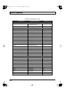
Although the target names indicated refer to EDIROL DV-7PR
and motion dive .tokyo, it is Control Change messages that are
actually transmitted.
For more on the correspondence between the target names and
Control Change numbers, refer to p. 181.
For more detailed information on the EDIROL DV-7PR and
motion dive .tokyo performance package, refer to the Owner’s
Manuals for each product.
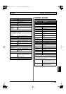
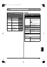
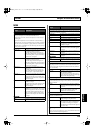
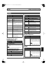
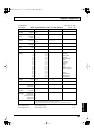
STRING CH (String Channel)
Some V-LINK compatible equipments such as the EDIROL DV-
7PR allow use only of A CH.
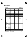
Parameter/
Range
Explanation
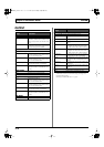
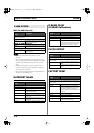
TRIGGR *2
Sets the point at which the virtual expression pedal’s action begins.
PATCH CHANGE Functions when patches are switched.
GK VOL Functions when the divided pickup’s vol-
ume knob is adjusted.
GK S1, S2 Functions when the divided pickup’s
DOWN/S1 or UP/S2 switch position is
changed.
CTL1–CTL4 Functions when the CTL 1, 2 buttons or foot
switch connected to CTL 3,4 jack are operat-
ed.
EXP Functions when the expression pedal con-
nected to EXP PEDAL jack are operated.
D BEAM V, H Functions when the vertical or horizontal
position is detected by the D Beam control-
ler.
RIBBON ACT, POS Functions when the ribbon controller is op-
erated by touch or when the position is de-
tected.
FC-300 EXP1, EXP2 Functions when the FC-300’s EXP PEDAL 1
or 2 is operated.
FC-300 CTL1, CTL2 Functions when the FC-300’s CTL1 or CTL2
is operated.
FC-300 E3/C3, CTL4,
E4/C5, CTL6, E5/C7,
CTL8
Functions when a pedal connected to the
FC-300’s E3/C3, CTL4, E4/C5, CTL6, E5/
C7, or CTL8 jacks is operated.
TIME *2
0–100 Adjusts the amount of time for the virtual
expression pedal to shift from the fully re-
leased position (pedal toe raised) to the fully
depressed position (pedal toe pressed
down).
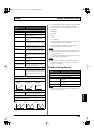
CURVE *2
This selects one of the three types that determines how the assumed
expression pedal changes.
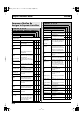
RATE *3
0–100
This determines the time spend for one cycle
of the assumed expression pedal.
FORM *3
This selects one of the three types that determines how the assumed
expression pedal should change.
LINEAR SLOW RISE FAST RISE
SAW
TRI
SIN
Parameter/
Range
Explanation
1st–6th
Selects the channel to be controlled with each string.
OFF No channel is controlled.
A CH Channel A of the V-LINK compatible device
is controlled.
B CH Channel B of the V-LINK compatible device
is controlled.
C CH MIDI Note plug-in is controlled.
VG-99_e.book 175 ページ 2007年7月5日 木曜日 午前9時22分