


173
SYSTEM Chapter 9 Parameter Guide
Chapter 9
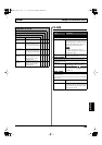
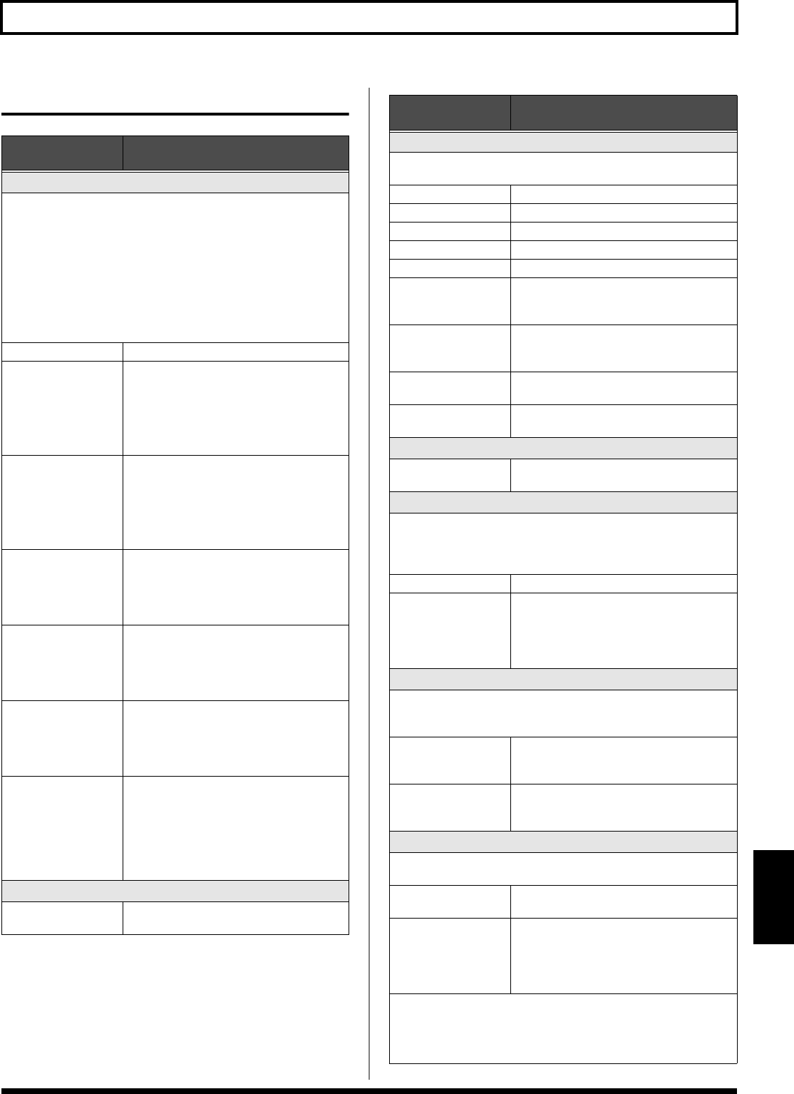
USB
Parameter/
Range
Explanation
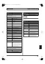
USB IN
This sets the point at which digital audio signals received via USB
(from your computer) are connected within the VG-99.
* Unless this is set to OFF, make sure the software is not set to thru for
audio signals.
* If the USB IN parameter is set to COSM GTR A, COSM GTR B, or
NORMAL PU, the setting automatically changes to MAIN & SUB the
next time the VG-99 is powered up. If you plan to use COSM GTR A,
COSM GTR B, or NORMAL PU, make the setting each time you turn
on the power to the VG-99.
OFF
The signals are not connected at any point.
COSM GTR A The signals are connected at the point where
the COSM GUITAR A is output.
The audio output from the computer, in-
stead of the COSM guitar sounds played by
the connected guitar, is input to the effects.
* POLY FX are not applied.
COSM GTR B The signals are connected at the point where
the COSM GUITAR B is output.
The audio output from the computer, in-
stead of the COSM guitar sounds played by
the connected guitar, is input to the effects.
* POLY FX are not applied.
NORMAL PU
The signals are connected at the normal
pickup input.
The audio output from the computer, in-
stead of the normal sounds played by the
connected guitar, is input to the effects.
MAIN OUT The signals are connected at the point where
MAIN OUT is output.
The signals from the VG-99’s MAIN OUT
and the audio output from the computer are
mixed and output.
SUB OUT The signals are connected at the point where
SUB OUT is output.
The signals from the VG-99’s SUB OUT and
the audio output from the computer are
mixed and output.
MAIN&SUB The signals are connected at the point where
both MAIN OUT and SUB OUT are output.
Each of the signals from the VG-99’s MAIN
OUT and the audio output from the com-
puter are mixed, SUB OUT and the audio
output from the computer are mixed from
the output.
IN LEVEL
0–200
Adjusts the volume level of the digital audio
received via USB (from the computer).
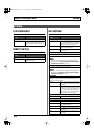
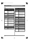
Parameter/
Range
Explanation
USB OUT
This sets the point internally within the VG-99 from which signals
are output via USB (to the computer).
COSM GTR A
The output from COSM GUITAR A is output.
COSM GTR B
The output from COSM GUITAR B is output.
NORMAL PU The normal pickup input is output.
CH A The output from Channel A is output.
CH B The output from Channel B is output.
MIXER (DRY) The signals that have been mixed with the
mixer, but before application of DELAY/
REVERB, are output.
MIXER The signals that have been mixed with the
mixer and have DELAY/REVERB applied
are output.
MAIN OUT The same signals as those from MAIN OUT
are output.
SUB OUT The same signals as those from SUB OUT
are output.
OUT LEVEL
0–200
Adjusts the volume level of the digital audio
output via USB (to the computer).
DRIVER MODE
This setting determines which operational mode is used, the mode
using the special driver contained on the included CD-ROM (AD-
VANC) or the mode using the OS’s (Windows/Mac OS) standard
driver (STANDRD).
STANDRD
This mode uses the OS’s standard USB driver.
ADVANC This mode uses the special driver contained
on the included CD-ROM
The mode using this driver allows you to
record, play back, and edit audio with high-
quality sound and stable timing.
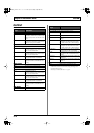
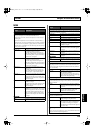
MON CMD (Monitor Command)
This setting determines whether or not the command (the Direct
Monitor command) controlling the Direct Monitor (described later)
setting is enabled.
DISABL The Direct Monitor command is disabled,
maintaining the Direct Monitor mode set by
the VG-99.
ENABLE The Direct Monitor command is enabled, al-
lowing the Direct Monitor mode to be
switched from an external device.
DIRECT MON (Direct Monitor)
Switches the output of the VG-99 sound to the PHONES jack, MAIN
OUT jacks, or SUB OUT jacks.
OFF Set this to Off if transmitting audio data in-
ternally through a computer (Thru).
ON The VG-99 sound is output. Set this to On
when using the VG-99 as a standalone de-
vice, without connecting to a computer
(only USB IN input sound will be output if
this is set to Off).
* This setting cannot be saved. It is set to ON when the power is turned
on.
* If you are using the special driver, you can control DIRECT MON On/
Off from ASIO 2.0-compatible application.
VG-99_e.book 173 ページ 2007年7月5日 木曜日 午前9時22分