


174
Chapter 9 Parameter Guide SYSTEM
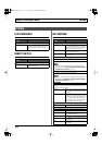
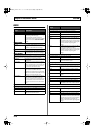
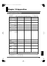
V-LINK
CLIP
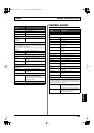
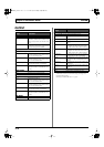
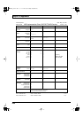
ASSIGN 1–2
V-LINK PATCH
Parameter/
Range
Explanation
This sets the Program Change messages transmitted when patches
are switched.
You can set different Program Changes in Channel A and Channel
B. The clips (video images) on the receiving device are switched by
these Program Change messages.
A ch/B ch PALETTE
OFF, 1–32
This sets the Bank Select number (CC#0,
#32).
A ch/B ch CLIP
OFF, 1–32
This sets the Program Change numbers.
Parameter/
Range
Explanation
These settings are necessary for controlling video using the guitar’s
performance data and messages from the VG-99’s controllers.
You can make up to two types of settings.
SOURCE
OFF
The V-LINK function is not assigned.
BEND Pitch bend messages
VELO Velocity messages
GK VOL GK-3 GK volume knob
GK S1 GK-3 DOWN/S1 switch
GK S2 GK-3 UP/S2 switch
CTL1 Control button1
CTL2 Control button2
EXP PEDAL Expression pedal connected to the EXP
PEDAL jack
CTL3 Footswitch connected to the CTL3,4 jack
(jack tip)
CTL4 Footswitch connected to the CTL3,4 jack
(jack ring)
D BEAM V D BEAM vertical movements
D BEAM H D BEAM horizontal movements
RIBBON RIBBON CONTROLLER
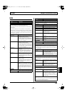
FC-300 EXP1 FC-300 expression pedal1
FC-300 EXPSW1 FC-300 expression pedal switch1
FC-300 EXP2 FC-300 expression pedal2
FC-300 EXPSW2 FC-300 expression pedal switch2
FC-300 CTL1 FC-300 control pedal1
FC-300 CTL2 FC-300 control pedal2
FC-300 E3/C3 FC-300 external expression pedal3/external
footswitch3
FC-300 CTL4 FC-300 external footswitch4
FC-300 E4/C5 FC-300 external expression pedal4/external
footswitch5
FC-300 CTL6 FC-300 external footswitch6
FC-300 E5/C7 FC-300 external expression pedal5/external
footswitch7
FC-300 CTL8 FC-300 external footswitch8
INTRNL PEDAL Internal pedal
WAVE PEDAL Wave pedal
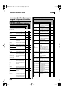
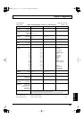
TARGET
Used in the motion dive .tokyo performance package.
COLOR EQ-FG Color foreground
COLOR EQ-BG Color background
SCRTCH SW Scratch switch
SPEED KNOB Speed knob
TOTAL FADER Total fader
CROSS FADER Cross fader
BPM SYNC BPM sync switch
CLIP LOOP Clip loop switch
ASSIGN KNOB Assignable knob
FADE TIME Fade time switch
VISUAL KNOB Visual plug-in control knob
AB SW A/B switch
TAP SW Tap switch
TOTAL SELECT Total select
FX SELECT Effect select
PLAY POS Play position
LOOP START Loop start position
LOOP END Loop end position
LAYER MODE Layer mode select
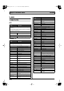
DV-7PR
PLAY SPEED Play speed
DISLV TIME Dissolve time
(time elapsed in switching video images)
T BAR T bar
COLOR Cb Color cb (Color difference signal)
COLOR Cr Color cr (Color difference signal)
BRIGHTNESS Brightness
VFX 1 Visual effects1
VFX 2 Visual effects2
VFX 3 Visual effects3
VFX 4 Visual effects4
OUTPUT FADE Output fade
DUAL STREAM Dual stream
MIN (Minimum) *1
0–127 Sets the lower limit in the range the param-
eter changes.
MAX (Maximum) *1
0–127 Sets the upper limit in the range the param-
eter changes.
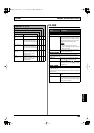
Parameter/
Range
Explanation
VG-99_e.book 174 ページ 2007年7月5日 木曜日 午前9時22分