


152 Chapter 12—Common Channel Functions
DM2000 Version 2—Owner’s Manual
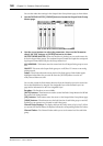
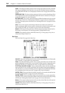
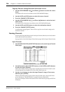
Fader: This indicates the fader position of the currently selected Input Channel. The fader
knob appears highlighted when the fader is set to 0.0 dB. The fader position is displayed
numerically below the fader. See “Setting Input Channel Levels” on page 90 for more infor-
mation.
SURROUND PAN: The Surround pan parameters for the currently selected Input Chan-
nel are displayed only when a Surround mode other than Stereo is selected. See “Using Sur-
round Pan” on page 97 for more information.
BUS ROUTING: This section contains Routing and Follow Pan buttons for the currently
selected Input Channel. See “Routing Input Channels” on page 93 for more information.
The Direct Out output patch can also be set. See “Patching Direct Outs” on page 81 for more
information.
AUX: These are the currently selected Input Channel’s Aux Send Level, On/Off, and
Pre/Post parameters. While a rotary control is selected, the Aux Send can be turned on and
off by pressing [ENTER]. See “Aux Sends” on page 110 for more information.
Meters: These meters indicate the levels of the currently selected Input Channel and its
horizontal or vertical partner. The metering position is displayed below them.
GROUP: These buttons indicate which Fader, Mute, EQ, or Comp group, if any, the cur-
rently selected Input Channel is in.
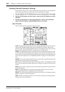
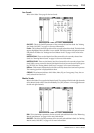
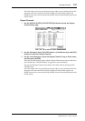
Bus Outs
This is the Fader View page for the Bus Outs.
ON/OFF: This is the On/Off parameter of the currently selected Bus Out. See “Muting Bus
Outs (ON/OFF)” on page 108 for more information.
Fader: This indicates the fader position of the currently selected Bus Out. The fader knob
appears highlighted when the fader is set to 0.0 dB. The fader position is displayed numer-
ically below the fader. See “Setting Bus Out Levels” on page 108 for more information.
TO ST PAN, ON/OFF & Fader: These are the Bus Out to Stereo Out Pan, On/Off, and
Fader parameters for the currently selected Bus Out. The fader knob appears highlighted
when the fader is set to 0.0 dB. The fader position is displayed numerically below the fader.
See “Sending Bus Outs to the Stereo Out” on page 109 for more information.
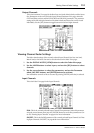
MATRIX PAN: These are the Matrix Send Pan controls for the currently selected Bus Out.
See “Panning Matrix Sends” on page 123 for more information.
MATRIX SEND: These are the Matrix Send Level controls for the currently selected Bus
Out. While a rotary control is selected, the Matrix Send can be turned on and off by pressing
[ENTER]. See “Setting Matrix Send Levels” on page 121 for more information.
Meters: These meters indicate the levels of the currently selected Bus Out and its partner.
The metering position is displayed below them.
GROUP: These buttons indicate which Fader, Mute, EQ, or Comp group, if any, the cur-
rently selected Bus Out is in.