


Control Surface 43
DM2000 Version 2—Owner’s Manual
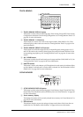
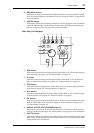
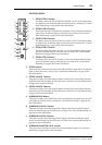
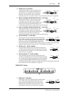
CONTROL ROOM
A STEREO 2TR D1 button
This button selects the 2TR IN DIGITAL AES/EBU 1 as the Control Room Mon-
itor signal source. Its indicator lights up when this source is selected. See “Control
Room Monitoring” on page 158 for more information.
B STEREO 2TR D2 button
This button selects the
2TR IN DIGITAL AES/EBU 2 as the Control Room Monitor
signal source. Its indicator lights up when this source is selected. See “Control
Room Monitoring” on page 158 for more information.
C STEREO 2TR D3 button
This button selects the
2TR IN DIGITAL COAXIAL 3 as the Control Room Moni-
tor signal source. Its indicator lights up when this source is selected. See “Control
Room Monitoring” on page 158 for more information.
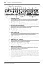
D STEREO 2TR A1 button
This button selects the
2TR IN ANALOG 1 as the Control Room Monitor signal
source. Its indicator lights up when this source is selected. See “Control Room
Monitoring” on page 158 for more information.
E STEREO 2TR A2 button
This button selects the
2TR IN ANALOG 2 as the Control Room Monitor signal
source. Its indicator lights up when this source is selected. See “Control Room
Monitoring” on page 158 for more information.
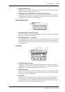
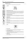
F STEREO button
This button selects the Stereo Out as the Control Room Monitor signal source. Its indicator
lights up when this source is selected. See “Control Room Monitoring” on page 158 for
more information.
G STEREO ASSIGN 1 button
This button is used to select the assigned Output Channel as the Control Room Monitor
signal source. Its indicator lights up when this source is selected. See “Control Room Setup”
on page 159 for more information.
H STEREO ASSIGN 2 button
This button is used to select the assigned Output Channel as the Control Room Monitor
signal source. Its indicator lights up when this source is selected. See “Control Room Setup”
on page 159 for more information.
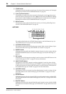
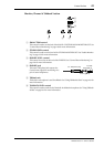
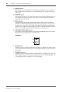
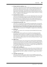
I SURROUND BUS button
This button is used to select the Bus Outs as the Surround Monitor signal source. Its indi-
cator lights up when this source is selected. See “Surround Monitoring” on page 160 for
more information.
J SURROUND ASSIGN 1 button
This button is used to select the assigned Slot’s Inputs as the Surround Monitor signal
source. Its indicator lights up when this source is selected. See “Surround Monitoring” on
page 160 for more information.
K SURROUND ASSIGN 2 button
This button is used to select the assigned Slot’s Inputs as the Surround Monitor signal
source. Its indicator lights up when this source is selected. See “Surround Monitoring” on
page 160 for more information.
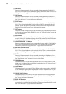
L SURROUND MONITOR LEVEL control
This control is used to adjust the level of the Surround Monitor signals. See “Surround
Monitoring” on page 160 for more information.
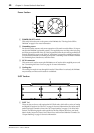
CONTROL ROOM
2TRD1 2TR A1
2TRD2 2TR A2
2TRD3STEREO
ASSIGN 1 ASSIGN2
ASSIGN 1 ASSIGN2
DIMMER
SMALL
MONO
SURROUND
MONITOR LEVEL
CONTROL ROOM LEVEL
BUS
STEREO
SURROUND
100
1 4
2 5
3 6
7 8
J
L
K
M
O
P
N
9