


GPI (General Purpose Interface) 265
DM2000 Version 2—Owner’s Manual
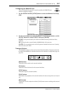
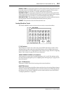
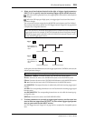
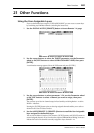
4 Select one of two buttons located to the right of trigger signal parameters
INPUT 1 & 2 to specify how the incoming trigger signals will be detected.
: When the switch is grounded (Low), the trigger signal is active and the selected param-
eter changes.
: When the GPI Input goes High (open), the trigger signal is active and the selected
parameter changes.
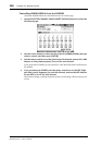
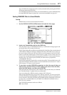
You can execute functions assigned to the MONITOR section buttons and User Defined
Keys, and turn channels on and off. See “GPI Trigger Source & Target List” on page 302 for
a complete list of assignable functions.
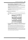
At this point, when the DM2000 receives the trigger signal at the CONTROL connector, the
selected parameter changes.
TALKBACK - SMALL: Functions the same as the MONITOR section buttons.
SR xxx: Functions the same as the SURROUND buttons in the MONITOR section.
CR xxx: Functions the same as the CONTROL ROOM buttons in the MONITOR section.
SM xxx: Functions the same as the STUDIO buttons in the MONITOR section.
xxx UNLATCH: The assigned function is enabled only while the incoming trigger signal
is active.
xxx ON: The corresponding channels turn on or off each time the incoming trigger signal
becomes active.
xxx ON UNLATCH: The corresponding channels turn on only while the incoming trig-
ger signal is active.
UDEFxxx: Functions the same as the USER DEFINED KEYS.
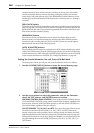
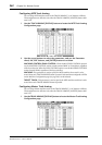
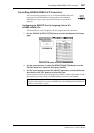
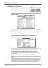
5 To select parameters or controls as trigger signal sources, use the cursor but-
tons to select an output from OUTPUT 1–8, then select trigger signal param-
eters as you would for the INPUT section.
See “GPI Trigger Source & Target List” on page 302 for a complete list of assignable param-
eters.
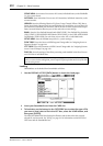
Note: “xxx UNLATCH” means that the assigned function is enabled only while the incoming
trigger signal is active. For example, if CH1 ON is selected, the channel on/off status changes
each time the trigger signal is detected. If CH1 ON UNLATCH is selected, Channel 1 turns
on only while the trigger signal is active.
Tip: Refer to the page 302 for a complete list of assignable parameters.
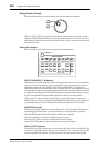
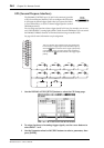
Input signals from
the CONTROL con-
nector
Executes the function.
Trigger =
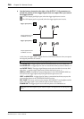
Input signals from
the CONTROL con-
nector
Trigger =
Executes the function.
Executes the function. Executes the function.