


264 Chapter 20—Remote Control
DM2000 Version 2—Owner’s Manual
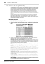
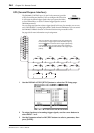
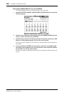
GPI (General Purpose Interface)
The DM2000’s CONTROL port (25-pin D-sub connector) provides
a GPI (General Purpose Interface). You can configure the GPI so that
it will output 8-channel trigger signals when you operate the faders
or User Defined Keys, or receive 2-channel trigger signals to control
DM2000 parameters.
You can assign any function to these trigger signals. In this way, for example, you can con-
trol a “RECORDING” warning light outside a studio from the DM2000, or you can control
the DM2000’s Talkback function or Dimmer function using an outside switch.
See page 350 for more information on pin assignment.
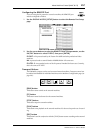
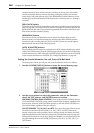
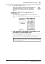
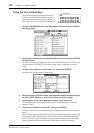
1 Use the DISPLAY ACCESS [SETUP] button to select the GPI Setup page.
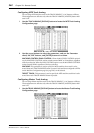
2 To assign functions to incoming trigger signals, use the cursor buttons to
select INPUT 1 or 2.
3 Use the Parameter wheel or INC/DEC buttons to select a parameter, then
press [ENTER].
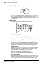
9 1 21 14 9 2 21 15
9 3 21 16 9 4 21 17
22 5 10 6
GPO0 GPO1 GPO2 GPO3
GPO4 GPO5 GPO6 GPO7
GPI0 GPI1
14
15
16
17
18
19
20
21
22
23
24
25
2
3
4
5
6
7
8
9
10
11
12
13
1
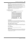
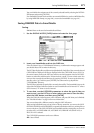
This is an example of the external circuit that operates GPI.
In this example, a trigger signal causes the LEDs to light up
when the button is selected as the trigger signal polarity
in the OUTPUT section. A trigger signal causes the LEDs to
turn off when the button is selected as the trigger signal
polarity.